


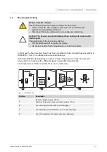


Connection, installation / mounting
Product manual 2CKA001473B8289
│
15
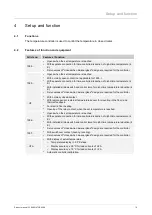
6.3
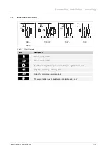
Electrical connection
N
N
L
L
1
N
N
L
L
1
2
2
1
2
1 1
N
N
L
L
1
16A
16A
16A
230 V
230 V
230 V
24 V
1094...
1095...
1095 UF
1097...
1096
Fig. 3:
Circuit diagrams
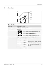
Icon
Assignment
Connections 24 V AC
Connections 24 V AC
Input for activating the temperature reduction (see night-time reduction)
Output for controlling the heating load
Output for controlling the cooling load
*
*
The sensor cable must be installed in a protective cable duct.


