background image

See our catalog at 

www.burrking.com

Contact us at 

[email protected]

BURR KING MFG. CO., INC.

1220 TAMARA LANE

WARSAW, MO 65355

WWW.BURRKING.COM

(660) 438-8998

(800) 621-2748

FAX (660) 438-8991


April 2000

Instruction for aligning the idler wheels on model 760 belt grinders

When idler wheels are removed and/or replaced they must be installed such that they are in proper 
alignment. Failure to properly align the idler wheels will result in premature failure of the wheels. 
Premature failure will be evidenced by outer diameters being excessively worn such that the wheels lose 
their factory crown, wear to a truncated form, or become out of balance. Misalignment results in wear that 
is analogous to front tire wear when the front steering mechanism of an automobile is miss aligned. The 
upper idler equates to the front wheels of the car. If either idler wheel is misaligned to each other or to the 
contact wheel excessive, and irregular wear will occur.

The upper and rear idler wheels must operate in the same plane. This means that when they are correctly 
aligned a plane passing through the radial center of the upper wheel will exactly pass through the radial 
center of the rear wheel. Machines are shipped from the factory with wheels of the same width. In 
example, the model 760 prior to mid 1999 was shipped with wheels that are 1.75 inches wide. Currently, 
model 760 machines are shipped with wheels that are 2.0 inches wide. The 1.5 and 2.0 inch wheels may 
be interchanged and/or mixed; however, if they are mixed their widths must be taking into account when 
performing this alignment. The model 760 contact wheel may be 0.5, 1.5, or 2.0 inches wide. Likewise 
the width of the contact wheel must be taken into account when performing this alignment.

Never perform maintenance or adjustments as described below on your model 760 without 
first disconnecting the machine from its source of electric power. Failure to observe this 
warning may lead to serious personal injury.

Procedure:  (disconnect electric power and remove the abrasive belt)
1. Install the rear idler such that its inside-bearing surface is approximately 0.06 inches out from the 

wheel support P/N 735. Secure the wheel with locking set screw P/N 25.

2. Install the upper wheel such that its inner bearing surface is approximately 0.06 inches out from its 

bearing support P/N 714. Secure the wheel with locking set screw P/N 25.

3. Loosen the retaining nut P/N 22 that locks the upper idler wheel adjusting screw P/N 721. Using 

screw P/N 721 adjust the upper idler wheel until a straight line representing the plane passing through 
the center of the upper idler exactly passes through the center of the contact wheel. This line 
represents the center of belt travel. Note: make certain that the bearing support is against the screw 
end of P/N 721.

4. Project a line from the upper idler outside rim to the outside rim of the rear idler. Adjust the tracking 

control P/N 711 until the wheels are exactly planar. That is their radial centers are aligned.

5. Repeat step 3 and 4 until both conditions are satisfied. That is the upper and rear idlers are aligned to 

each other and both wheels are aligned to the contact wheel.

6. Tighten the locking nut on P/N 721.
7. Install a new abrasive belt. Roll the belt manually to assure that it will maintain coarse tracking. If the 

belt does not track manually, repeat the prior steps until it does.  If after repeating these steps the belt 
still will not track the machine requires other maintenance and/or one or both idler wheels require 
replacing. The wheels should be replaced in pairs.

8. Apply electric power to the machine and verify that the tracking control P/N 711 will sweep the belt 

across the face of the contact wheel. At least ½ inch adjustment in both directions from center should 
be possible.

Summary of Contents for 760

Page 1: ...BURR KING MFG CO INC 1220 Tamara Lane Warsaw MO 65355 www burrking com 660 438 8998 800 621 2748 Fax 660 438 8991 BURR KING MODEL 760 THREE WHEEL GRINDER MODEL 760 INSTRUCTION MANUAL Model 72110 Shown ...

Page 2: ... King Manufacturing Company Inc may elect to make on site service and or repairs necessary to return the product to serviceable condition To assure prompt warranty service it is necessary that you complete and return the below warranty information to Burr King Manufacturing Company Inc please FAX or MAIL at your convenience Product model _______________________ Serial number ______________________...

Page 3: ......

Page 4: ...tion to all operators and to those persons who might be in the immediate vicinity of the subject equipment 11 Use work piece holding devices when ever possible that diminish the possibility that persons will come in contact with moving machine pieces or spark debris output from the machine 12 Use spark and debris arresting apparatus Such apparatus should be connected to the machine so as to contai...

Page 5: ...follow the operating requirements provided by the manufacturer of these materials Rotational Speed Warning Contact Wheels Scope Contact wheels manufactured by Burr King Manufacturing Company Inc which have rubber or urethane tires Examples include but are not limited to stock codes 202 302 402 502 702 802 902 1002 1202 and variants Variants have stock codes that begin with the base number i e 802 ...

Page 6: ...ould be protected from excessive noise does levels as prescribed in OSHA regulation 29 piece 1910 95 titled Occupational Noise Exposure ROTATING EQUIPMENT CAN BE DANGEROUS TO OPERATORS AND THOSE WHO MAY BE IN ITS IMMEDIATE OPERATING VICINITY IT IS THE ABSOLUTE AND DIRECT RESPONSIBILITY OF PURCHASERS MANAGERS AND OPERATORS OF THIS EQUIPMENT TO UNDERSTAND AND OBEY THE FOREGOING MINIMUM OPERATING SAF...

Page 7: ...ring 4 Do not modify or defeat any AC wiring safety feature In example do not remove the grounding pin on the AC plug 5 Verify that you have received a warranty card parts lists catalog and Operator and Operating Area Safety Instructions 6 Complete the warranty card and return it to Burr King Manufacturing 7 Verify that the various guards for the machine are in place and functional See the parts l...

Page 8: ...rse up from the floor you must correct this unsafe condition by changing the main drive motor rotation direction WARNING FIRST DISCONNECT THE MACHINE FROM ITS AC POWER SOURCE A COMPETENT ELECTRICIAN SHOULD PERFORM ALL ELECTRICAL WORK ON THE MODEL 760 1 Reversed the motor direction of a three phase motor by reversing any two legs of the input power lines 2 Reverse the motor direction of a single ph...

Page 9: ...xplosion fire hazard Do not use stone or vitreous wheels on the model 760 To do so will create an operator safety hazard Do use eye hand face arm leg feet and body protection that is adequate to protect against flying debris forcibly ejected work pieces broken abrasive belts etc Do train operators and others in safe operating practices Post these or equivalent instructions such that they are avail...

Page 10: ...cribed below on your model 760 without first disconnecting the machine from its source of electric power Failure to observe this warning may lead to serious personal injury Procedure disconnect electric power and remove the abrasive belt 1 Install the rear idler such that its inside bearing surface is approximately 0 06 inches out from the wheel support P N 735 Secure the wheel with locking set sc...

Page 11: ... 49 24 10 48 53 51 55 10 56 24 22 32 52 745 MODEL 760 PARTS LIST 17 16 14 15 24 10 10 18 31 3 29 34 42 42 40 34 42 42 33 40 8 43 44 45 46 39 26 29 3 27 2 13 11 12 10 9 7 20 21 35 34 19 24 4 3 5 6 28 25 41 10 23 38 31 37 36 1 30 33 34 35 18 10 BURR KING 1220 TAMARA LANE WARSAW MO 65355 ...

Page 12: ...NG CONTACT WHEEL ASSY 6 6 1 4 20 x 1 1 2 FH SOC 7 702 CONTACT WHEEL SMOOTH 8 703 3 GUARD CONTACT WHEEL 9 30 1 4 20x1 SHCS 10 5 WASHER 1 4 AN 11 704 1B BRACKET PLATEN 12 209 SCREW 1 4 20 X 3 4 ALLEN HEAD 13 704 1A PLATEN 14 15 WASHER 5 16 LOCK SPLIT 15 13 SCREW 10 24 x 3 4 SOC HD CAP 16 705 1 ARM WORKREST SUPPORT 17 706 1 WORKREST ANTI TILT 18 31 1 4 20x1 1 4 SHCS 19 6 0014 PIN 1 8 X 3 4 ROLL PLTED...

Page 13: ...7 5 6 4 3 1 2 8 9 11 10 MAG STARTER PARTS LIST BURR KING 1220 TAMARA LANE WARSAW MO 65355 ...

Page 14: ... 37 BOLT 5 16 18x3 4 HEX HEAD 4 5 5 WASHER 1 4 AN 4 6 209 SCREW 1 4 20 X 3 4 ALLEN HEAD 4 7 4 0013 NUT KEP 1 4 20 4 8 MS2A3 MS4A3 MS2B3 MS4B3 3 4HP 1HP 220V 3 4HP 1HP 440V 1 5HP 3HP 220V 1 5HP 3HP 440V 1 9 775 CONNECTOR 3 8 STR LIQ TIGHT 1 10 776 CONNECTOR 3 8 90 DEG LIQ TIGHT 1 11 020 CONDUIT 3 8 LIQUID TIGHT 1 BURR KING 1220 TAMARA LANE WARSAW MO 65355 ...

Page 15: ...7 7 6 5 5 6 4 9 4 8 5 3 4 5 6 1 2 7 9 4 15 10 13 14 11 16 1 5 3 HP 15 12 10 13 11 14 3 4 1 HP VARI SPEED SINGLE PHASE BURR KING 1220 TAMARA LANE WARSAW MO 65355 ...

Page 16: ...725C 150B 1725C 1 HP MOTOR 1 5 HP MOTOR 1 9 37 BOLT 5 16 18x3 4 HEX HEAD 4 10 015 1 017 120V CORD 220V CORD 1 11 020 CONDUIT 3 8 LIQUIDTIGHT 1 12 864 1 CONT 115 220V 0 75 1HP 1 13 775 CONNECTOR 3 8 STR LIQ TIGHT 1 14 776 CONNECTOR 3 8 90 DEG LIQ TIGHT 1 15 643 RELIEF STRAIN 3 8 90 DEG 1 16 862 3 CONT 115 220V 1 5 3HP 1 ADD TO CONTROLLER ITEM NO PART NUMBER DESCRIPTION QTY 12 9974 6 LINE FILTER 1 1...

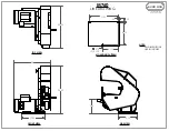
Page 17: ... 25 TOP VIEW 25 50 24 12 25 FRONT VIEW 9 75 7 5 MOUNTING PATTERN SIDE VIEW 11 25 8 75 50 50 6 175 375 3 PLCS M760 LINE DRAWING NOTE ALL DIMENSIONS ARE IN INCHES BURR KING 1220 TAMARA LANE WARSAW MO 65355 ...

Reviews: