8.
All three phase electrical installations must include a magnetic starter. Magnetic starters protect motors
from “double phasing”, overheating, etc. thereby reducing the risk of damage to the equipment and/or
fire hazard to your facility. Three phase motors are not warranted if used without a magnetic starter or
other suitable device.
Functional operating instructions for the Model 1051 Tube Finisher
The Model 1051 was fully tested and verified to comply with requirements prior to shipping from the factory.
No adjustments should be necessary. You should perform the following steps:
1.
Machine securely bolted to its table, pedestal, and/or floor point connect the AC power to its source.
2.
Ensure the wheels are firmly tightened to the spindle. A finishing wheel running in reverse rotation can
unscrew from the spindle, creating a serious personnel safety hazard. Insure that the Model 1051 spindle
operates CCW when viewed from the right side of the machine.
3.
Engage the motor. The wheel should rotate smoothly in a CCW direction with the front face of the
finishing wheel moving toward the floor. If either of these conditions are not met turn the machine OFF
immediately.
4.
If the Model 1051 runs in reverse direction you must correct this by changing the main drive motor
rotation direction.
FIRST DISCONNECT THE MACHINE FROM ITS AC POWER SOURCE. A
COMPETENT ELECTRICIAN SHOULD PERFORM ALL ELECTRICAL WORK ON THE
MODEL 1050.
If your Model 1051 is equipped with variable speed control the wheel speed can be adjusted using the speed
control that will be mounted on the motor or on a separate control box.
Operating instructions for the Model 1051 Tube Finisher
Prior to daily operation follow the steps listed below:
1.
Verify the machine is in good working order. Check
for unsafe conditions or damaged parts and repair or
replace prior to operation. Tag out machine if any
issues cannot be resolved.
2.
Clean work area and machine. Start with a clean area
around the machine.
3.
Check brush for damage. Replace if needed.
4.
Adjust safety shield over wheel and allow clearance for
operation.
5.
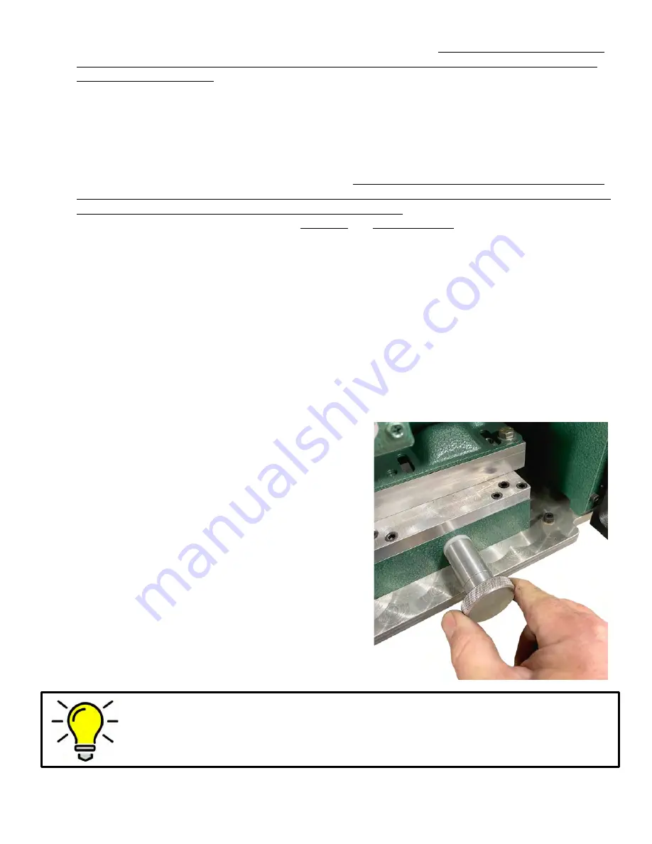
Using the knob on the base of the motor, adjust the
wheel forward towards the tool rest. Make sure the
brush has a gap no greater than a 1/8”. Replace brush if
the workrest cannot be adjusted within specifications.
The M1051 has over two inches of forward travel.
6.
Adjust the tool rest by loosing the lever and adjusting to
centerline of wheel for general deburring operation.
The tool rest has a flat support and a v-notched rest.
TIP: Adjustment of the brush
Your M1051 can accept wheels up to 10” in diameter and up to 3” in width. The machine
has been designed with a tool free wheel adjustment to move the brush forward inside of the
stationary wheel guard. The M1051 has two inches of free travel.


