


57
IX. Service
A.
General.
Inspection and service must be conducted
annually. Turn off electrical power and gas supply while
conducting service or maintenance. Follow instructions
TO TURN OFF GAS TO APPLIANCE. See Lighting/
Operating Instructions on inside of Front Removable
Door.
Label all wires prior to disconnection when
servicing controls. Wiring errors can cause
improper and dangerous operation. Verify proper
operation after servicing.
B.
Maintenance of Low Water Cut-off (if used).
Follow
instruction manual provided with low water cut off.
If model 805, see Installation and Operating manual
for Hydrostat 3200, packed in envelope taped to top
of boiler for packaged boilers and in parts and control
carton for KD boilers for maintenance.
C.
Vent System.
Check for:
1. obstructions
2. accumulations of soot
3. deterioration of vent pipe or vent accessories due to
condensation or other reasons
4. proper support—no sags, particularly in horizontal
runs
5. tightness of joints. Remove all accumulations of
soot with wire brush and vacuum
Remove all obstructions. Replace all deteriorated parts
and support properly. Seal all joints.
D.
Remove Main Burners
for cleaning, changing orifice
plugs, or repairs.
1. Shut down gas boiler in accordance with Lighting/
Operating Instructions on inside of Front Removable
Door. Close Manual Shut-off Valve.
2. Remove Front Removable Door. Raise Lower Front
Tie Bar.
3. Disconnect ignition system.
4. Remove burner access panel(s).
5. Mark location of Main Burner with Pilot Bracket on
manifold.
6. Remove hitch pin clips from Main Burner Orifices.
7. Hold Main Burner on throat. Lift slightly to raise
rear of burner. Push to rear of boiler until burner
clears Main Burner Orifice. Lift burners out.
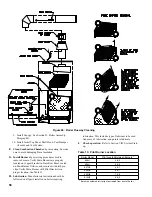
8. Check burners to be sure they do not contain foreign
matter or restrictions. Clean burners with a soft
bristle brush, blow any dirt out with compressed air
or use a vacuum cleaner. See Figure 48.
E.
Clean Boiler Flueways.
See Figure 48.
1. Shut down gas boiler in accordance with Lighting/
Operating Instructions on inside of Front Removable
Door. Close Manual Shut-off Valve.
2. Disconnect vent system. Remove Draft Hood.
3. Remove Jacket Top Panel.
4. Remove Canopy from top of boiler.
5. Remove flue baffles. Refer to Figure 48 for
instructions on how to remove baffles from
flueways. Remove any accumulated scale or soot.
6. Thoroughly clean flueways with flue brush,
removing all scale and soot. See Figure 48.
7. Clean boiler heating surface accessible from
combustion chamber with straight handle wire
brush.
8. Reinsert baffles into flueways by reversing steps
given in Figure 48. Tabs at top of each baffle should
rest on top of flue pins.
Service on this boiler should be undertaken only by trained and skilled personnel from a qualified service
agency. Inspections should be performed at intervals specified in this manual. Maintain manual in a
legible condition.
Keep boiler area clear and free of combustible materials, gasoline and other flammable vapors and
liquids.
Do not place any obstructions in boiler room that will hinder flow of combustion and ventilation air.
The service instructions contained in this manual are in addition to the instructions provided by the
manufacturer of the boiler components. Follow component manufacturer’s instructions. Component
manufacturer’s instructions were provided with the boiler. Contact component manufacturer for replace-
ment if instructions are missing. Do not install, start up, operate, maintain or service this boiler without
reading and understanding all of the component instructions. Do not allow the boiler to operate with
altered, disconnected or jumpered components. Only use replacement components identical to those
originally supplied by Burnham Commercial.
Summary of Contents for 805H
Page 15: ...15 Figure 8 Jacket Assembly...
Page 16: ...16 Figure 9 EP Control Installation...
Page 18: ...18 Figure 10 Schematic Gas Piping 24V Standing Pilot 806H 807HE...
Page 19: ...19 Figure 11 Main Gas Piping Intermittent Ignition EI...
Page 20: ...20 Figure 12 Schematic Pilot Piping Honeywell EI USA...
Page 22: ...22 Figure 14 Schematic Gas Piping EP Control System Natural Gas Only 806H 810HE...
Page 23: ...23 Figure 15 Schematic Gas Piping EP CSD 1 Control System 808HE 810HE...
Page 36: ...36 Figure 27 Wiring Diagram Standing Pilot 24V Continuous Circulation 806H 807HE...
Page 37: ...37 Figure 28 Wiring Diagram Standing Pilot 24V Intermittent Circulation 806H 807HE...
Page 39: ...39 Figure 29 Wiring Diagram Honeywell EI USA Canada 805 Only with Hydrostat 3200 Control...
Page 40: ...40 Figure 30 Wiring Diagram Honeywell EI USA Continuous Circulation 806 810...
Page 41: ...41 Figure 31 Wiring Diagram Honeywell EI USA Intermittent Circulation 806 810...
Page 50: ...50 Figure 40 Lighting Instructions 24V Standing Pilot...
Page 51: ...51 Figure 41 Operating Instructions EI...
Page 52: ...52 Figure 42 Operating Instructions EP...
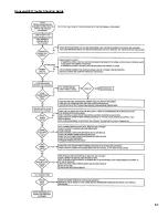
Page 61: ...61 Honeywell EI Trouble Shooting Guide...
Page 76: ...76...
Page 78: ...78...
Page 82: ...82...
Page 83: ...83...
Page 84: ...84...