Burmester Top Line Phono preamp 100 Owner'S Manual Download Page 14


11 


Auto Adjust


Some pickups show a pretty high level tolerance between the left and right channel. In this 
case the 100 is equipped with an automatic level adjust function. This function measures 
the channel difference and automatically adjusts it. This requires that your record player is 
configured correctly.  

PLEASE NOTICE:

 During the Auto Adjust measurement the unit will set up the technically 

optimal input amplification. You can change this setting, if another input amplification 
sounds better to you.  
 
How to approach: 
Select a moderate volume, household noise level at maximum. 
Put the test record on your record player. Now lower the pickup on the record. The preamp 
requires a 1kHz sine wave stereo signal. As soon as you hear the measurement signal, 
activate the measurement by pushing the 

AUTO ADJUST switch key


(22) 

up for 

approximately 2 seconds. 
During the measurement process the 

AUTO ADJ ON LED (12)

 will flash. 

After incorrectly finishing the adjust process the 

AUTO ADJ ON LED (12)

 will stop flashing 

and the 

AUTO ADJ OFF LED (12)

 will illuminate. 

After correctly finishing the adjust process the 

AUTO ADJ ON LED (12)

  will stop flashing 

and will illuminate constantly. 
In case of incorrectly finishing you should check your record player if the right track was 
selected, the connectors for any errors and the properties of the 100 preamp. 
 
After correctly finishing the adjust process you will be able to deactivate it by pushing the 

AUTO ADJUST switch key (22)

 down. Pushing up the 

AUTO ADJUST switch key (22) 

will 

activate the function any time. 


Defaults


To recover factory settings the 100 preamp offers the option to load the default parameters. 
All adjustments will be deleted, including the Auto Adjust.  
With a combination of keys on the front panel similar to the activation of the volume control 
the default parameters can be loaded: 

1.

 Use the 

POWER switch (23)

 to switch the 100 into standby mode. 

2.

 Now, simultaneously, you have to pull down the 

DIM / VU-Meter switch key (19),


AUTO 

ADJUST switch key  (22)

  and the 

ADC switch key (21).

  Hold these three keys 

simultaneously while you now switch on the 100 preamp with the 

POWER switch (23)

 
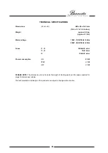
After correctly loaded default parameters, the settings are as followed:  


Load:

 75

 / 120pF 


Gain:

 66dB / 46dB 


Output:

 0dB 


Subsonic:

 ON 


Variable:

 OFF 


VU-Meter:

 Mono 


DIM:

 maximum brightness 


ADC:

 OFF 


Auto Adjust:

 OFF 

 
Previous Auto Adjust parameters will be deleted by loading the default parameters and 
need to be calibrated again. 
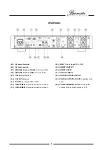


ERRORDISPLAY


Since the 100 Phono preamp is not equipped with a classic display, the 

POWER LED (24)

 will indicate any errors by 

flashing. Should an error occur, the 100 preamp will switch itself into standby mode. 
 
In case of a flashing 

POWER LED (24)

 in any color we ask you to switch of the unit and disconnect it from the power 

grid. After approximately 10 seconds try again to switch on the 100 preamp. If there is still any error, please contact 
your authorized dealer. 

Summary of Contents for Top Line Phono preamp 100

Page 1: ......

Page 2: ...degree of operating flexibility We recommend reading this user manual in its entirety before initial operation It will enable you to make full use of all capabilities of this outstanding audiophile instrument Should you have any further questions please contact your dealer or us directly Talk to us about your special requests even if they seem out of the ordinary We happily accept technical reason...

Page 3: ...ne arm cable 7 REMOTE 7 BURLINK 7 OPERATING CONTROLS 8 AC Mains Switch 8 POWER Switch 8 Input Selection 8 Input Resistance MC 8 Input Capacitance MM 8 Input Amplification 9 Subsonic Filter 9 Output Amplification 9 VU Meter 9 Display Brightness 9 ADC Activation 9 ADC Sample Frequency 10 Phase Reversal 10 Volume Control 10 Auto Adjust 11 Defaults 11 ERRORDISPLAY 11 REMOTE CONTROL 12 BURLINK 13 CONNE...

Page 4: ...tic channel calibration AUTO ADJUST selectable if the channels of the pickup system have different sound levels compensation is possible up to 6dB difference between the channels Selectable volume control for direct use with power amps or active loudspeakers Increasing of output level to 6dB possible for operating the preamp with amplifiers with low input sensitivity 180 phase reversal of the bala...

Page 5: ...g in case the unit needs to be shipped in the future Setting up Too low or too high temperatures may cause damage inside of the preamp Therefore we recommend you leave the unit to adapt to room temperature before using it for the first time Carefully remove the unit from its packaging and set it up in an appropriate location To protect the Phono preamp 100 from overheating make sure that the locat...

Page 6: ...r commands of remote control 7 VOLUME LED lights up for variable volume control 19 DIM VU METER switch key to control the 8 VU METER displays the load of the ADC dim and VU Meter functions 9 OVERFLOW LED shows distortion of the ADC 20 ADC OFF LED lights when the ADC is off 10 VU METER LEDs display the mode of the VU Meter 21 ADC switch key for ADC operation 11 ADC LEDs display the sample rate of t...

Page 7: ...RLINK interface USB with check LEDs 37 USB OUT INPUT 29 OUTPUT unbalanced 38 DIGITAL OUTPUT USB OUT 30 OUTPUT balanced 39 DIGITAL OUTPUT A D OUT for signals of the 31 INPUT 2 as equipped MC or MM ADC 32 GND SCREW for ground connection of input 2 40 PHASE REVERSAL switch to change the 33 GND SCREW for ground connection of input 1 polarity of the XLR output pins by 180 ...

Page 8: ...e AC power cord into the AC mains terminal 25 and plug it into the wall outlet Make sure that the POWER switch 23 is set to the off position Switch the AC mains switch 26 to ON position The POWER LED 24 will instantly light green During these seconds in which the POWER LED 24 lights green the power supply will measure your mains voltage and take the necessary steps to work properly After successfu...

Page 9: ... Please use BURMESTER XLR RCA adapters only Wiring of the XLR RCA adapter plugs RCA XLR GROUNDING Screw The GND screws 32 and 33 serve for the unbalanced connection between your record player and the preamp To link the ground cable loose the GND screw clamp the GND wire of your record player between the two washers and tighten the GND screw until the GND wire can not slip out Don t use any other t...

Page 10: ...ds a 75 Ω coaxial cable with RCA connectors NOTICE Do not connect the RCA 39 output to an analog input of an amplifier severe damage to your equipment or your ears may be the result Since the USB plug is also operable as an input the Phono preamp offers two digital outputs USB OUT 38 to connect a digital recording unit or a Digital Analog Converter These two outputs supply the digital signal from ...

Page 11: ...efore If you for example press the DISC button and then use the STATION buttons they will not have any affect on the 100 Phono preamp The chosen input will be displayed via the INPUT LEDS 1 on the left side of the front panel In addition to the input the MC MM LED will show what kind of module is equipped on that input The settings for each input are stored separately Thus if you switch between in...

Page 12: ...U Meter to display the modulation amplitude of the ADC Analog Digital Converter If the VU Meter displays 0dBFS the maximum level of 2 Volts is present at the ADC input This level must never be exceeded Otherwise digital distortion will occur Adjust the input amplification of the 100 to a level that 3dBFS beginning of the red area is not reached The OVERFLOW LED 9 is an additional display for the d...

Page 13: ...00 into the desired position Volume Control The 100 Phono preamp has the unique option to be operated with a volume control This options allows the direct use of the preamp with power amps or active loudspeakers When the unit operates in variable volume mode the VOLUME LED 7 lights up WARNING When the VOLUME LED 7 is not lit you must not connect the 100 Phono preamp to a power amp or active loudsp...

Page 14: ...tly finishing the adjust process you will be able to deactivate it by pushing the AUTO ADJUST switch key 22 down Pushing up the AUTO ADJUST switch key 22 will activate the function any time Defaults To recover factory settings the 100 preamp offers the option to load the default parameters All adjustments will be deleted including the Auto Adjust With a combination of keys on the front panel simil...

Page 15: ...djust the brightness of the display in 4 steps These steps vary between max brightness and off If you choose the option off the display will only light up when you change anything This gives you a feedback about the changes you are applying When you are done with your changes the display will go blank again after a couple of seconds Output amplification Longer pressing the button SUBT changes the ...

Page 16: ...POWON r switches the unit on POWOFF r switches the unit to standby mode INP r toggles the inputs of the preamp INP r toggles the inputs of the preamp INP1 r switches to input 1 INP2 r switches to input 2 VOLUP r increases the volume by one step VOLDN r decreases the volume by one step ADC r switches the ADC on and toggles the sampling frequency between 48kHz 96kHz and 192kHz ADC_OFF r switches the...

Page 17: ...toggles the overall amplification between 0dB and 6dB OUT_0DB r switches the overall amplification to 0dB OUT_6DB r switches the overall amplification to 6dB AUDOADJ_CAL r starts the Auto Adjust calibration AUDOADJ_ON r switches the Auto Adjust on AUDOADJ_OFF r switches the Auto Adjust off VUM r toggles the VU Meter settings between off left right mono TYPE r shows the type of the unit SNR r show ...

Page 18: ...Since the power supply automatically adjusts to your ac mains voltage it is save to use the 100 with every established mains voltage Comm Operation Before installation switch off all other components of your hifi system Switch them back on only after making sure that all connections have been made correctly and completely Never try to operate the equipment when it has obviously been damaged or if ...

Page 19: ...e housing with a wet cloth or chemical cleaning agent Always make sure that no liquid gets into the housing This symbol on the equipment points to important notes which can be found in the owner s manual This symbol on or inside the equipment warns of dangerously high voltage If the unit is to be put out of operation definitively take it to a local recycling plant for a disposal which is not harmf...

Page 20: ...17 ...

Page 21: ...18 ...

Page 22: ...19 ...

Page 23: ...00V 120V 50Hz 60Hz 200V 240V 50Hz 60Hz Fuses F1 F2 500mA E slow F3 F4 1A E slow F5 50mA E slow Power consumption ON 25 W STBY 1 W OFF 1 W PLEASE NOTE The dimensions do not include the length of binding posts and the space needed for plugs of interconnect cables The technical data and design of this product are subject to change without notice ...

Page 24: ......

Reviews: