background image

31

Notizen

LEVEL SWITCH 8110 • - kontaktloser Schalter

41765-DE-140211

Summary of Contents for LEVEL SWITCH 8110

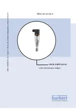
Page 1: ...Operating Instructions LEVEL SWITCH 8110 contactless electronic switch...

Page 2: ...uct description 3 1 Configuration 6 3 2 Principle of operation 6 3 3 Adjustment 7 3 4 Storage and transport 7 4 Mounting 4 1 General instructions 9 4 2 Mounting instructions 11 5 Connecting to power s...

Page 3: ...tip note This symbol indicates helpful additional information Caution If this warning is ignored faults or malfunctions can result Warning If this warning is ignored injury to persons and or serious...

Page 4: ...use Inappropriate or incorrect use of the instrument can give rise to application specific hazards e g vessel overfill or damage to system components through incorrect mounting or adjustment 2 4 Gener...

Page 5: ...safety approval markings and safety tips on the device must be observed 2 6 CE conformity The device fulfills the legal requirements of the applicable EC guide lines By affixing the CE marking we conf...

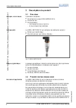
Page 6: ...icle number Serial number Technical data Article numbers documentation 3 2 Principle of operation LEVEL SWITCH 8110 is a point level sensor with tuning fork for point level detection It is designed fo...

Page 7: ...he integrated electronics evaluates the level signal and outputs a switching signal With this switching signal a connected device can be operated directly e g a warning system a pump etc The data for...

Page 8: ...kings on the outside Unless otherwise indicated the packages must be stored only under the following conditions Not in the open Dry and dust free Not exposed to corrosive media Protected against solar...

Page 9: ...ameplate In general LEVEL SWITCH 8110 can be installed in any position The instrument only has to be mounted in such a way that the tuning fork is at the height of the desired switching point Keep in...

Page 10: ...able entry Rain and condensation water can thus drain off This applies mainly to outdoor mounting as well as installation in areas where high humidity is expected e g through cleaning pro cesses or on...

Page 11: ...Before welding unscrew LEVEL SWITCH 8110 and remove the rub ber ring from the welded socket The welded socket is provided with a marking notch For horizontal mounting weld the socket with the notch f...

Page 12: ...easurement signals can be generated For this reason mount LEVEL SWITCH 8110 at a position in the vessel where no disturbanc es e g from filling openings agitators etc can occur To make sure the tuning...

Page 13: ...oss section Depending on the plug connec tion you have to select the outer diameter of the cable respectively so that the seal effect of the cable gland is ensured Valve plug ISO 4400 4 5 7 mm Valve p...

Page 14: ...Fig 8 Connection valve plug ISO 4400 1 Pressure screw 2 Pressure disc 3 Seal ring 4 Fixing screw 5 Seal washer 6 Plug housing 7 Plug insert 8 Profile seal 9 Control lamp 10 LEVEL SWITCH 8110 Valve pl...

Page 15: ...d without an intermediately connected load because the electronics would be destroyed if con nected directly to the mains It is not suitable for connection to low voltage PLC inputs Examples for typic...

Page 16: ...L SWITCH 8110 contactless electronic switch 41765 EN 140211 RL RL 3 2 1 3 2 1 N L1 L1 N Max Min PE PE Fig 10 Wiring plan contactless electronic switch with valve plug ISO 4400 PE Protective ground RL...

Page 17: ...r simula tion of the output signal which can be activated magnetically Please proceed as follows Hold the test magnet accessory against the circle symbol with the label TEST on the instrument housing...

Page 18: ...owing chart provides an overview of the switching conditions depending on the set mode and the level Level Switching sta tus Control lamp Yellow cov erage Control lamp Green voltage indication Control...

Page 19: ...d Check the voltage supply and the ca ble connection Electronics de fective Exchange the instrument or send it in for repair Red signal lamp lights switching output high im pedance Error with the elec...

Page 20: ...g companies We use recyclable materials and have designed the parts to be easily separable WEEE directive 2002 96 EG This instrument is not subject to the WEEE directive 2002 96 EG and the respective...

Page 21: ...mp 2 PN 16 DIN 32676 ISO 2852 316L bolting DN 25 PN 40 bolting DN 40 PN 40 bolting DN 50 PN 25 SMS DN 38 PN 6 Max torque process fitting Thread G NPT 50 Nm 37 lbf ft Thread G NPT 75 Nm 55 lbf ft Threa...

Page 22: ...n 40 150 C 40 302 F 1 2 40 C 40 F 100 C 212 F 120 C 248 F 140 C 284 F 40 C 104 F 60 C 140 F 0 C 32 F 20 C 68 F 150 C 302 F 80 C 176 F 20 C 4 F 0 C 32 F 70 C 158 F 40 C 40 F Fig 31 Dependendency ambien...

Page 23: ...Electromechanical data Valve plug ISO 4400 Wire cross section 1 5 mm 0 06 in Outer cable diameter 4 5 7 mm 0 18 0 28 in Valve plug ISO 4400 with IDC method of termination Wire cross section for wire...

Page 24: ...5 27 mm 1 06 36 mm 1 42 28 mm 1 1 1 2 42 mm 1 65 SW 32 mm 1 26 38 mm 1 5 17 mm 0 67 G1 2 1 2 NPT 11 mm 0 43 L 3 L 60 mm 2 36 Fig 32 LEVEL SWITCH 8110 standard version thread G NPT 1 Thread G DIN ISO 2...

Page 25: ...2 27 mm 1 06 31 7 mm 1 25 42 mm 1 65 42 mm 1 65 28 mm 1 10 58 mm 2 28 58 mm 2 28 21 3 mm 0 84 Fig 33 LEVEL SWITCH 8110 standard version thread G G1 NPT 1 NPT 1 Thread G G1 DIN ISO 228 1 NPT or 1 NPT v...

Page 26: ...3 4 NPT G1 1 NPT 11 mm 0 43 L 101 mm 3 98 21 3 mm 0 84 Fig 34 LEVEL SWITCH 8110 high temperature version 1 Thread G G G1 DIN ISO 228 1 NPT NPT or 1 NPT valve plug ISO 4400 2 Clamp valve plug ISO 4400...

Page 27: ...40211 1 2 3 38 mm 1 5 L 115 mm 4 53 11 mm 0 43 105 mm 4 13 L 21 3 mm 0 84 Fig 35 LEVEL SWITCH 8110 high temperature version 1 Bolting valve plug ISO 4400 2 SMS 1145 valve plug ISO 4400 3 Switching poi...

Page 28: ...The smart choice of Fluid Control Systems www burkert com 41765 EN 140211...

Page 29: ...Bedienungsanleitung LEVEL SWITCH 8110 kontaktloser Schalter...

Page 30: ...6 CE Konformit t 5 3 Produktbeschreibung 3 1 Aufbau 6 3 2 Arbeitsweise 6 3 3 Bedienung 7 3 4 Lagerung und Transport 7 4 Montieren 4 1 Allgemeine Hinweise 9 4 2 Montagehinweise 11 5 An die Spannungsve...

Page 31: ...ichtbeachten dieses Warnhinweises k nnen St run gen oder Fehlfunktionen die Folge sein Warnung Bei Nichtbeachten dieses Warnhinweises kann ein Perso nenschaden und oder ein schwerer Ger teschaden die...

Page 32: ...i nicht sachgerechter oder nicht bestimmungsgem er Verwen dung k nnen von diesem Ger t anwendungsspezifische Gefahren ausgehen so z B ein berlauf des Beh lters oder Sch den an Anlagenteilen durch fals...

Page 33: ...beachten 2 5 Sicherheitskennzeichen am Ger t Die auf dem Ger t angebrachten Sicherheitskennzeichen und hin weise sind zu beachten 2 6 CE Konformit t Das Ger t erf llt die gesetzlichen Anforderungen de...

Page 34: ...Dokumentation 3 2 Arbeitsweise Der LEVEL SWITCH 8110 ist ein Grenzstandsensor mit Schwingga bel zur Grenzstanderfassung Er ist konzipiert f r industrielle Eins tze in allen Bereichen der Verfah renst...

Page 35: ...ellt ein Schaltsignal zur Verf gung Mit diesem Schaltsignal k nnen Sie ein nachgeschaltetes Ger t direkt bet tigen z B eine Warneinrichtung eine Pumpe etc Die Daten f r die Spannungsversorgung finden...

Page 36: ...bewahren Packst cke sofern nicht anders angegeben nur unter folgenden Bedingungen lagern Nicht im Freien aufbewahren Trocken und staubfrei lagern Keinen aggressiven Medien aussetzen Vor Sonneneinstrah...

Page 37: ...f dem Typschild Grunds tzlich kann der LEVEL SWITCH 8110 in jeder beliebigen La ge eingebaut werden Das Ger t muss lediglich so montiert werden dass sich die Schwinggabel auf H he des gew nschten Scha...

Page 38: ...en f hren Regen und Kondenswasser k nnen so abtropfen Dies gilt vor allem bei Montage im Freien in R umen in denen mit Feuchtigkeit zu rechnen ist z B durch Reini gungsprozesse oder an gek hlten bzw b...

Page 39: ...ewinde des LEVEL SWITCH 8110 Diese Flachdichtung wird bei Verwendung des Einschwei stutzens mit frontb ndiger Dichtung nicht ben tigt Vor dem Einschwei en m ssen Sie den LEVEL SWITCH 8110 herausschrau...

Page 40: ...ten deshalb eine bestimmte L nge nicht berschreiten 30 mm 1 18 Abb 6 Anhaftende F llg ter Wenn der LEVEL SWITCH 8110 im Bef llstrom eingebaut ist kann dies zu unerw nschten Fehlmessungen f hren Montie...

Page 41: ...schirmtes Kabel verwendet werden Verwenden Sie Kabel mit rundem Querschnitt Je nach Steckeran schluss m ssen Sie den Kabelau endurchmesser entsprechend w hlen damit die Dichtwirkung der Kabelverschrau...

Page 42: ...2 Abb 7 bersicht ber die Anschlussvarianten 1 Ventilstecker ISO 4400 2 Ventilstecker ISO 4400 mit Schneidklemmtechnik Ventilstecker ISO 4400 Bei dieser Steckervariante k nnen Sie ein handels bliches K...

Page 43: ...ungsschraube 5 Dichtscheibe 6 Steckergeh use 7 Steckereinsatz 8 Profildichtung 9 Kontrollleuchte 10 LEVEL SWITCH 8110 Ventilstecker QuickOn ISO 4400 Bei dieser Steckervariante k nnen Sie ein handels b...

Page 44: ...geschaltete Last betrieben werden da der Elektronikeinsatz bei direktem Anschluss an das Netz zerst rt wird Nicht zum Anschluss an Niederspannungs SPS Eing nge geeignet Beispiele f r typische Anwendun...

Page 45: ...anschlie en LEVEL SWITCH 8110 kontaktloser Schalter 41765 DE 140211 RL RL 3 2 1 3 2 1 N L1 L1 N Max Min PE PE Abb 10 Anschlussplan kontaktloser Schalter bei Ventilstecker ISO 4400 PE Schutzerde RL La...

Page 46: ...0 hat eine integrierte Funktion zur Simulation des Ausgangssignals die magnetisch aktiviert werden kann Gehen Sie folgenderma en vor Pr fmagnet Zubeh r an das Kreissymbol mit der Aufschrift TEST auf d...

Page 47: ...e folgende Tabelle gibt eine bersicht ber die Schaltzust nde in Abh ngigkeit von der eingestellten Betriebsart und dem F llstand F llstand Schaltzustand Kontrollleuchte Gelb Bede ckungszustand Kontrol...

Page 48: ...terbrochen berpr fen Sie die Spannungsversor gung und die Kabelverbindung Elektronik defekt Ger t austauschen bzw zur Repara tur einsenden Rote Kontroll leuchte leuchtet Schaltausgang ist hochohmig Fe...

Page 49: ...rzu die Elektronik leicht trennbar gestaltet und verwenden recyclebare Werkstoffe WEEE Richtlinie 2002 96 EG Das vorliegende Ger t unterliegt nicht der WEEE Richtlinie 2002 96 EG und den entsprechende...

Page 50: ...Clamp 2 PN 16 DIN 32676 ISO 2852 316L Rohrverschraubung DN 25 PN 40 Rohrverschraubung DN 40 PN 40 Rohrverschraubung DN 50 PN 25 SMS DN 38 PN 6 Max Anzugsmoment Prozessanschluss Gewinde G NPT 50 Nm 37...

Page 51: ...F 1 2 40 C 40 F 100 C 212 F 120 C 248 F 140 C 284 F 40 C 104 F 60 C 140 F 0 C 32 F 20 C 68 F 150 C 302 F 80 C 176 F 20 C 4 F 0 C 32 F 70 C 158 F 40 C 40 F Abb 31 Abh ngigkeit Umgebungstemperatur zu P...

Page 52: ...Min 10 mA Max 250 mA Elektromechanische Daten Ventilstecker ISO 4400 Aderquerschnitt 1 5 mm 0 06 in Kabelau endurchmesser 4 5 7 mm 0 18 0 28 in Ventilstecker ISO 4400 mit Schneidklemmtechnik Aderquer...

Page 53: ...1 06 36 mm 1 42 28 mm 1 1 1 2 42 mm 1 65 SW 32 mm 1 26 38 mm 1 5 17 mm 0 67 G1 2 1 2 NPT 11 mm 0 43 L 3 L 60 mm 2 36 Abb 32 LEVEL SWITCH 8110 Standardausf hrung Gewinde G NPT 1 Gewinde G DIN ISO 228...

Page 54: ...m 1 06 31 7 mm 1 25 42 mm 1 65 42 mm 1 65 28 mm 1 10 58 mm 2 28 58 mm 2 28 21 3 mm 0 84 Abb 33 LEVEL SWITCH 8110 Standardausf hrung Gewinde G G1 NPT 1 NPT 1 Gewinde G G1 DIN ISO 228 1 NPT oder 1 NPT V...

Page 55: ...NPT G1 1 NPT 11 mm 0 43 L 101 mm 3 98 21 3 mm 0 84 Abb 34 LEVEL SWITCH 8110 Hochtemperaturausf hrung 1 Gewinde G G G1 DIN ISO 228 1 NPT NPT oder 1 NPT Ventilstecker ISO 4400 2 Clamp Ventilstecker ISO...

Page 56: ...mm 1 5 L 115 mm 4 53 11 mm 0 43 105 mm 4 13 L 21 3 mm 0 84 Abb 35 LEVEL SWITCH 8110 Hochtemperaturausf hrung 1 Rohrverschraubung Ventilstecker ISO 4400 2 SMS 1145 Ventilstecker ISO 4400 3 Schaltpunkt...

Page 57: ...29 Notizen LEVEL SWITCH 8110 kontaktloser Schalter 41765 DE 140211...

Page 58: ...30 Notizen LEVEL SWITCH 8110 kontaktloser Schalter 41765 DE 140211...

Page 59: ...31 Notizen LEVEL SWITCH 8110 kontaktloser Schalter 41765 DE 140211...

Page 60: ...The smart choice of Fluid Control Systems www buerkert com 41765 DE 140211...

Page 61: ...Mise en service LEVEL SWITCH 8110 sortie lectronique statique...

Page 62: ...ription du produit 3 1 Structure 6 3 2 Proc d de fonctionnement 6 3 3 R glage et configuration 7 3 4 Stockage et transport 7 4 Monter 4 1 Remarques g n rales 9 4 2 Consignes de montage 11 5 Raccordeme...

Page 63: ...de cette recommandation peut entra ner des pannes ou des d fauts de fonctionnement Avertissement Le non respect de cette instruction peut porter pr judice la personne manipulant l appareil et ou peut...

Page 64: ...hef des transformations ou modifications sur l appareil 2 3 Avertissement contre les utilisations incorrectes Un usage non conforme ou non appropri de l appareil peut engen drer des risques sp cifique...

Page 65: ...consignes et des signalisations de s curit appos es sur l appareil 2 5 Caract ristiques de s curit sur l appareil Les caract ristiques et remarques de s curit se trouvant sur l appa reil sont respecte...

Page 66: ...s d articles documentation 3 2 Proc d de fonctionnement Le LEVEL SWITCH 8110 est un d tecteur de niveau lames vibrantes destin la d tection de niveau Il est con u pour les applications industrielles d...

Page 67: ...tation Le LEVEL SWITCH 8110 est un appareil compact c est dire qu il peut fonctionner sans exploitation externe L lectronique int gr e exploite le signal niveau et d livre un signal de commutation qui...

Page 68: ...t respecter les marquages de positionnement et de stockage appos s l ext rieur Sauf autre indication entreposer les colis en respectant les condi tions suivantes Ne pas entreposer l ext rieur Entrepos...

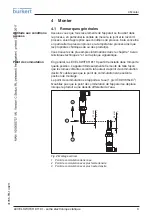
Page 69: ...la plaque signal tique En g n ral le LEVEL SWITCH 8110 peut tre install dans n importe quelle position L appareil doit seulement tre mont de telle fa on que les lames vibrantes soient la hauteur du p...

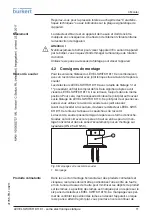
Page 70: ...pe vers le bas Ainsi l eau de pluie ou de condensat pourra s goutter Cela concerne en particulier les montages l ex t rieur ou dans des lieux o il faut s attendre de l humidit due par exemple des proc...

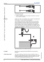
Page 71: ...retrouve toujours dans la m me position Pour cela il est n cessaire d enlever le joint plat se trouvant sur le filetage du LEVEL SWITCH 8110 Ce joint plat n est pas n ces saire si vous utilisez le ra...

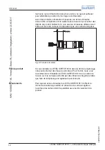
Page 72: ...sser ne d passent pas une certaine longueur 30 mm 1 18 Fig 6 Produits colmatants Si vous installez le LEVEL SWITCH 8110 dans le flot de remplissage cela peut entra ner des mesures erron es Pour l vite...

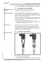
Page 73: ...ction du type de connecteur utilis pour garantir l tan ch it au presse toupe Connecteur type lectrovanne ISO 4400 4 5 7 mm Connecteur type lectrovanne ISO 4400 avec raccordement selon la technique bor...

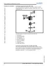
Page 74: ...type lectrovanne ISO 4400 1 Vis pression 2 Rondelle de pression 3 Anneau d tanch it 4 Vis de fixation 5 Joint d tanch it plat 6 Bo tier du connecteur 7 Insert du connecteur 8 Joint profil 9 T moin de...

Page 75: ...t pas fonctionner sans charge interm diaire un bran chement direct au secteur d truirait le pr amplificateur Ne convient pas au branchement des entr es d API basse tension Exemples d applications typi...

Page 76: ...e lectronique statique 41765 FR 140211 RL RL 3 2 1 3 2 1 N L1 L1 N Max Min PE PE Fig 10 Sch ma de raccordement sortie lectronique statique pour connecteur type lectrovanne ISO 4400 PE Terre de protect...

Page 77: ...ie du capteur haute imp dance 6 2 Simulation Le LEVEL SWITCH 8110 a une fonction int gr e qui peut tre activ e magn tiquement pour la simulation du signal de sortie Proc dez comme suit Maintenir l aim...

Page 78: ...nne un aper u des tats de commuta tion en fonction du mode de fonctionnement r gl et du niveau Niveau tat de commu tation T moin de contr le Jaune tat de l immersion T moin de contr le Vert Indication...

Page 79: ...Contr lez l alimentation et la liaison des c bles lectronique d fectueuse Remplacer l appareil ou le retourner au service r paration T moin rouge al lum sortie de commutation a une valeur oh mique lev...

Page 80: ...utilis s sont recyclables Directive DEEE 2002 96 CE Le pr sent appareil n est pas soumis la directive DEEE 2002 96 CE et aux lois nationales respectives Apportez l appareil directement une entreprise...

Page 81: ...lamp 2 PN 16 DIN 32676 ISO 2852 316L raccord union DN 25 PN 40 raccord union DN 40 PN 40 raccord union DN 50 PN 25 SMS DN 38 PN 6 Couple de serrage maxi raccord process Filetage G NPT 50 Nm 37 lbf ft...

Page 82: ...0 F 100 C 212 F 120 C 248 F 140 C 284 F 40 C 104 F 60 C 140 F 0 C 32 F 20 C 68 F 150 C 302 F 80 C 176 F 20 C 4 F 0 C 32 F 70 C 158 F 40 C 40 F Fig 31 D pendance entre temp rature ambiante et temp ratu...

Page 83: ...ques Connecteur type lectrovanne ISO 4400 Section des conducteurs 1 5 mm 0 06 in Diam tre ext rieur du c ble 4 5 7 mm 0 18 0 28 in Connecteur type lectrovanne ISO 4400 avec technique de borne guilloti...

Page 84: ...mm 1 1 1 2 42 mm 1 65 SW 32 mm 1 26 38 mm 1 5 17 mm 0 67 G1 2 1 2 NPT 11 mm 0 43 L 3 L 60 mm 2 36 Fig 32 LEVEL SWITCH 8110 version standard Filetage G NPT 1 Filetage G DIN ISO 228 1 NPT connecteur typ...

Page 85: ...mm 1 65 42 mm 1 65 28 mm 1 10 58 mm 2 28 58 mm 2 28 21 3 mm 0 84 Fig 33 LEVEL SWITCH 8110 version standard Filetage G G1 NPT 1 NPT 1 Filetage G G1 DIN ISO 228 1 NPT ou 1 NPT connecteur type lectrovan...

Page 86: ...L 101 mm 3 98 21 3 mm 0 84 Fig 34 LEVEL SWITCH 8110 version haute temp rature 1 Filetage G G G1 DIN ISO 228 1 NPT NPT ou 1 NPT connecteur type lectrovanne ISO 4400 2 Clamp connecteur type lectrovanne...

Page 87: ...53 11 mm 0 43 105 mm 4 13 L 21 3 mm 0 84 Fig 35 LEVEL SWITCH 8110 version haute temp rature 1 Raccord union connecteur type lectrovanne ISO 4400 2 SMS 1145 connecteur de type lectrovanne ISO 4400 3 P...

Page 88: ...The smart choice of Fluid Control Systems www burkert com 41765 FR 140211...

Reviews: