background image

Introduction 


ARC Plus Version 3 Instruction Manual 


connectivity.  Installation and operation are nearly identical to the ARC Plus system, with 
relevant differences noted in this manual.  

Front Panel 

Note: Se

ARC Plus SL

 for a description of the ARC Plus SL front panel features. 

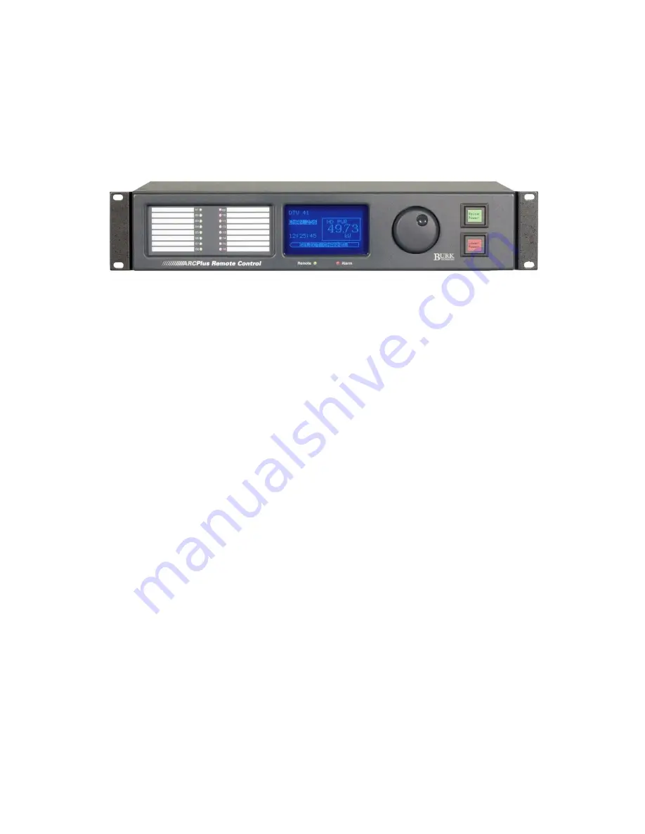
ARC Plus front panel 

Status LEDs 

Bicolor status LEDs provide visual indicators for status conditions, alarm activity, maintenance 
mode state, and link status for any site in the system.  

Vacuum Fluorescent Display (VFD) 

Shows meter conditions, alarm and event messages, and displays menu functions. The bottom 
row of the VFD shows the available menu options.  

Jog Wheel 

Facilitates front panel navigation. Rotate the jog wheel to sites, channels or menu options. Press 
the jog wheel to accept the selection highlighted on-screen. To exit the menus and return to the 
channel display, press and hold the jog wheel. 


Command Buttons 

Backlit command buttons are used for issuing commands and running or stopping macros. Each 
raise command, lower command, macro start and macro stop function may be assigned a user-
defined label and backlight color (green, red, amber or no color) for ease of operation.  

Remote LED 

Maintenance mode indicator. Illuminates green when the unit is remote mode (the unit will 
issue commands). Illuminates red when the unit is in maintenance mode (commands are 
disabled).  

Alarm LED 

Indicates alarm activity. Illuminates red when there is an alarm at the local site (default). May 
also be configured to indicate an alarm at any site in the ARC Plus network.  

Summary of Contents for ARC Plus

Page 1: ...ARC Plus Version 3 Instruction Manual ARC Plus ARC Plus SL AutoLoad Plus Software Rev B ARC Plus firmware version 3 0 3 4 AutoLoad Plus software version 3 1 130 ...

Page 2: ...igation 83 Redesigned smartphone interface to carry over the updated look and new features of the web interface 88 Easy to set automatic actions when channels cross limits or change state 54 63 Ability to set meter and status values directly from a macro without using a virtual channel 71 Ability to run two different macros using a single channel s raise lower buttons 71 New macro features includi...

Page 3: ...Plus Rear Panel 10 Modem DB 9M 10 ARC 16 DB 9M 10 Ethernet RJ 45 10 PLUSBUS RJ 45 11 Alarm 11 Failsafe 11 Audio 11 ESI Status 11 Set Line RJ 11 11 Plus X Ethernet I O 11 PlusConnect Direct Transmitter Interfaces 12 AutoLoad Plus Software 13 Enhanced Speech Interface ESI Plus 13 AutoPilot 2010 Software 14 Web based monitoring and control 15 Software and Firmware Updates 15 System Security 15 Hardwa...

Page 4: ...e appropriate rear panel connectors 20 Connecting Command Channels on the Plus X Integrated Command Relay Unit 20 Command Channel Connector Pinouts 20 Connecting an ARC 16 to the ARC Plus 21 Protecting Against Transients and Power Surges 21 Important Safety Information 21 Maintenance Mode 21 ARC Plus 22 ARC Plus SL 22 Power Recovery Behavior 22 Plus X ICRU Models 22 PlusBus ICRU Models 22 Configur...

Page 5: ...Delay Macros 33 Restore Relay States 33 Timeout Settings 34 Front Panel Behavior 34 ARC Plus and ARC Plus SL 35 ARC Plus Only 35 Screen Saver Settings 35 Alarms 36 ARC Plus 36 ARC Plus SL 36 Events 37 Primary Backup ESI Configuration 38 Modem Settings 39 AutoPilot 2010 Authorization Code 40 Hiding Unused Channels 41 Configuring an ARC Plus Network Multi Site Installations 41 Adding Sites to the Ne...

Page 6: ...Timing 49 Decimal Places 49 Setting the Meter Channel Source 50 Meter Graph Tab 51 Meter Alarms Tab 52 Delayed Alarm Reporting 52 Rearm Delay 52 Enabling Disabling Alarms 53 Setting Limits 53 Meter Actions Tab 54 Meter Notifications Tab 55 Meter Display Tab 56 Meter Speech Labels Tab 57 Calibrating Analog Inputs 57 Configuring Status Inputs 59 Status Channels Tab 59 Inverting a Status Channel 59 S...

Page 7: ...eating Macros 70 General Macro Expressions 71 Macro Expressions for Channel Values and Site Conditions 71 Macro Expressions for Date and Time Functions 72 Macro Expressions for Reading and Manipulating Variables 72 Macro Expressions for Running Stopping Other Macros 72 Other Macro Expressions 73 Scheduling the Macro 73 Programming Calendar Times 74 Configuring Macro Email Templates 75 Saving and N...

Page 8: ...nt Panel Graph Settings 80 Setting Metering Channel Alarm Delays 81 Configuring Status Channels 81 Configuring Command Channels 81 Hiding Channels from Display 81 ESI Configuration 81 Configuring Call and Answer Settings 82 Using the ESI Plus in Local Mode 82 Adjusting System Settings 82 Adjusting the Date and Time 82 Changing the Network Configuration 82 Viewing Firmware Version MAC address and m...

Page 9: ...alling the ESI 90 Receiving Dialout Alarm Notifications 91 ESI Plus operation 91 Site Selection 91 Channel Selection and Meter Readings 92 Issuing Commands 92 Reviewing Status Conditions 92 Reviewing Alarms 93 Running Macros 93 Audio Input Monitoring 94 Editing Master Phone Numbers 94 Muting Alarms 95 Onboard Help 95 Command Timeouts 96 Disconnecting 96 Using the ESI in Local Mode 96 ESI Plus Comm...

Page 10: ...rol central monitoring and or distributed access to more than 1 000 sites Users can manage the system via front panel web browser and optional telephone and software interfaces in any combination Multi site ARC Plus networks allow site to site control from the front panel of any ARC Plus or automatic coordination of multiple facilities via onboard macros ARC Plus Model The core of the ARC Plus sys...

Page 11: ...navigation Rotate the jog wheel to sites channels or menu options Press the jog wheel to accept the selection highlighted on screen To exit the menus and return to the channel display press and hold the jog wheel Command Buttons Backlit command buttons are used for issuing commands and running or stopping macros Each raise command lower command macro start and macro stop function may be assigned a...

Page 12: ...any site in the ARC Plus network see page 34 ARC Plus Rear Panel The rear panel of the ARC Plus facilitates connections to the LAN WAN integrated input and integrated command relay units a telephone line if an ESI is installed an ARC 16 if applicable an optional dial up modem and 100 to 240VAC power ARC Plus rear panel Modem DB 9M Provides external dial up modem connectivity for optional AutoPilot...

Page 13: ...oss of the ARC Plus network link The relay is latched closed when the network link is present Audio RCA input accepts audio source for remote monitoring via optional ESI Plus Enhanced Speech Interface over phone line ESI Status Provides diagnostic information during ESI Plus operation Set Line RJ 11 Allows connection of a telephone for local ESI Plus operation use the set jack and connection of a ...

Page 14: ... a direct digital connection to various transmitters without parallel wiring PlusConnect models are available for many popular models For a complete list of supported transmitters visit www burk com To install your PlusConnect follow the instructions in your product s manual The installation procedure is similar to installing any Plus X Ethernet I O device ...

Page 15: ...ndard on ARC Plus Stand Alone systems and optional on all other ARC Plus systems It provides dial in monitoring and control and dialout alarm notifications via a phone line and DTMF tones All site channel and macro labels are user specified using a large selection of pre recorded vocabulary Although an ESI Plus cannot be installed directly onboard the ARC Plus SL alarms on the ARC Plus SL can trig...

Page 16: ...ectivity allows simultaneous control of multiple sites while optional dial up modem connectivity provides a means to access single sites from outside the LAN AutoPilot 2010 provides a customizable GUI logging and automatic report generation network and SNMP monitoring and integration of remote security cameras Details are included in the AutoPilot 2010 instructions ...

Page 17: ... mobile For more on the web interface see page Error Bookmark not defined Software and Firmware Updates Periodic updates to ARC Plus software and firmware along with release notes are made available at www burk com To be notified when new versions are available sign up for email updates by clicking the Email Updates link on the Burk Technology web site System Security The ARC Plus protocol contain...

Page 18: ...isplay 2 Rotate the jog wheel until Config is selected and press the jog wheel to enter the configuration menu Select the System submenu and then select Network 3 Enter the private IP public IP and port values that will identify the ARC Plus as a unique device on the network The private IP is the IP address you will use to access the ARC Plus on your company LAN WAN The public IP address is used w...

Page 19: ...s link when it appears 2 Right click and select Properties for the network connection you will use to connect to the ARC Plus SL 3 Locate and select TCP IPv4 Click Properties Select Use the following IP address and enter an IP address in the range of 192 168 0 x other than 192 168 0 100 Press OK The ARC Plus SL default IP address is 192 168 0 100 For initial configuration access your network adapt...

Page 20: ... of your ARC Plus where prompted Note Some PlusConnect models are configured via telnet or a serial connection See your PlusConnect manual for more information Add your Device to the ARC Plus Once the Plus X device is configured for your network you will need to add it to the ARC Plus using AutoLoad Plus If you have not already installed AutoLoad Plus please do so now The current version of AutoLo...

Page 21: ...ling your Plus X devices click OK to close the Plus X Devices dialog You will see your new channels in the AutoLoad Plus channel tabs for your ARC Plus Note Be sure to save your AutoLoad Plus settings after assigning Plus X channels Connecting Analog and Status Inputs on the Plus X Integrated Input Unit Input Channel Pinouts Each Plus X Integrated Input Unit IIU connects up to 16 metering inputs 1...

Page 22: ...on the Plus X Integrated Command Relay Unit Command Channel Connector Pinouts The Plus X Integrated Command Relay Unit ICRU connects 8 raise and 8 lower channels using two identical 24 pin connector blocks Raise channels connect to the left set of 24 pins on the rear panel and lower channels connect to the right set of 24 pins so shown below Close up of Form C contacts on the ICRU rear panel Each ...

Page 23: ... dial up telephone control or via an external dialup modem external surge protection on the phone line is strongly recommended The Burk Technology TS 1 is designed specifically for this purpose External protection for the Ethernet connection is also recommended Important Safety Information Maintenance Mode Prior to performing any maintenance on connected site equipment operators MUST engage mainte...

Page 24: ...ting the jog wheel to OFF and pressing the jog wheel to accept The REMOTE LED on the front panel of the unit turns green and the MAINT flag disappears ARC Plus SL On the ARC Plus SL toggle maintenance mode by pressing the front panel REMOTE button A green REMOTE LED indicates the unit is in remote mode the unit will issue commands and a red REMOTE LED indicates the unit is in maintenance mode the ...

Page 25: ...anges are loaded directly to the unit Note Only System level users can access AutoLoad Plus The site administrator s will be able to define access levels for each individual user Software Installation Connecting to the ARC Plus To modify ARC Plus settings using AutoLoad Plus start by launching AutoLoad Plus AutoLoad Plus will prompt for connection settings Enter the IP address and your user name a...

Page 26: ... the settings will populate in AutoLoad Plus Press the Save toolbar icon to save the configuration to the ARC Plus Uploading Firmware Important Uploading firmware causes any latching relays to release when the ARC Plus unit restarts The relay state will be restored after the process is complete To load firmware to the ARC Plus use the ARC Plus Firmware Loader The firmware loader is installed with ...

Page 27: ...me set of usernames and passwords is used for each application Usernames may contain up to 32 characters Administrators can manage users and privileges by selecting Users from the Edit Settings menu To add a new user click the Add button You will be prompted to assign the new user a name and password Once the new user appears on the user list assign privileges by selecting an option from the Level...

Page 28: ... Time Settings To change the date and time settings for the ARC Plus choose Time Settings from the Edit Settings menu This opens the Time Settings dialog The General tab allows you to adjust the date display format time zone and the abbreviations used for the time zone If the ARC Plus location observes Daylight Saving Time check the box for DST To synchronize the time with your local PC press the ...

Page 29: ...e Edit Settings menu This will open the Network Settings dialog If you are unsure of the settings to use contact your network administrator Important After clicking the OK button in the Network Settings dialog AutoLoad will immediately commit your changes and reconnect to the ARC Plus Note In order to reference a mail server by host name instead of IP address a DNS Server is required If your firew...

Page 30: ...to normal An alarm is cleared A new event is logged To configure SNMP settings click SNMP Agent Settings from the Edit Settings menu You can enable or disable traps and configure the IP address or hostname and port for up to four SNMP managers SNMP Agent Settings Custom SNMP Traps The ARC Plus can send user defined SNMP traps for use with certain third party applications This functionality is not ...

Page 31: ... have configured status and metering channels Configuring Email Alarm Notifications Email Settings Email Settings To set up email notification and dialout notification lists choose Alarm Notifications from the Edit Settings menu This opens the Alarm Notifications dialog Before setting up list members enter the hostname or IP address of the mail server and the server port usually 25 If referencing ...

Page 32: ...appropriate personnel To create an email list click the Email Lists tab Click the Add button plus sign icon to the right of the Email Lists column and enter the name of your first list where prompted Then click the Add plus sign button to the right of the Email Addresses column and add email addresses to the list until complete When you are done you can click the Test Email button envelope icon to...

Page 33: ... Master Phone Numbers for information on programming the master dialout list Dialout Lists Dialout Lists To set up your dialout lists navigate to the Dialout Lists tab Click the Add button plus sign icon to the right of the Dialout Lists column and enter the name of your first list where prompted Then click the Add button plus sign icon to the right of the Phone Numbers column and assign telephone...

Page 34: ... tolerance conditions even if not alarmed The color of the LED is configurable as red green or off Compatibility mode shows the first 16 status channels of the ARC Plus where an illuminated red LED indicates a status high condition To configure the operation mode of the LEDs and set up colors and condition assignments in mapping mode choose Front Panel LEDs from the Edit Settings menu Select Mappi...

Page 35: ...f tolerance conditions Delay Macros Check the Delay macros box to prevent any macros from running during the specified duration after startup This feature can be used to prevent macros from using readings from equipment that has not yet stabilized or sending commands to equipment that has not yet come back online Restore Relay States For older systems installed with legacy PlusBus ICRU units the R...

Page 36: ...tain connection errors AutoLoad Plus AutoPilot 2010 and the ARC Plus will log events and or display error messages Timeout durations are user configurable in the Timeouts tab Note In a multi site ARC Plus network be sure that the Link Loss Timeout setting is the same value for each site in the network This will prevent false Remote unit missing alarms Front Panel Behavior Front Panel The front pan...

Page 37: ...ath uncleared alarms and show the date and time they were cleared If you want the status report to show status off and status on messages for every channel check the box marked Show all status conditions Otherwise the front panel status report will only include status on messages Screen Saver Settings Screen Saver On ARC Plus systems the front panel vacuum fluorescent display VFD may be configured...

Page 38: ...ice becoming disconnected To configure email notifications of system alarms email server settings and at least one email notification list must be configured see Configuring Email Alarm Notifications In order to select a dialout list an ESI Plus must be installed and there must be at least one dialout notification list created see Configuring Dialout Alarm Notifications ARC Plus SL The System emai...

Page 39: ... place on the system You can control what types of events are recorded by checking or unchecking the items in the list on the Events tab Note Depending on how you configure your ARC Plus some activities may generate a high volume of events For example running macros frequently will generate many macro events Configure the ARC Plus events accordingly to best suit your needs ...

Page 40: ...alled in a network of ARC Plus systems the ESI tab allows you to configure primary and backup sites When an alarm occurs on the local ARC Plus and dialout notification is enabled for that alarm the ARC Plus will initiate dialout using the ESI Plus installed at the site designated as Primary ESI site The ESI site timeout setting determines how long the ARC Plus will wait for a response from the pri...

Page 41: ...modem to the ARC Plus enter the modem s initialization string and connection speed where prompted The Inactivity timeout determines how long the ARC Plus will wait after the last data exchange before disconnecting a modem connection To allow the modem to be used for dialout notifications and incoming calls leave the Dialout on alarm and Answer calls boxes checked Disabling these options is a means...

Page 42: ...0 an authorization code is provided for one 1 ARC Plus unit Enter the authorization code where prompted in order to begin using AutoPilot 2010 with this ARC Plus Note The ARC Plus will retain the authorization code after upgrading firmware resetting factory settings or cycling power However keeping a record of your authorization code is strongly recommended ...

Page 43: ... Configuring an ARC Plus Network Multi Site Installations When more than one ARC Plus unit is installed within an organization grouping the units together in a single ARC Plus network offers the advantage of site to site control where commands and macros issued by one unit can control equipment connected to another unit It also allows alarms from one site to appear on the front panel of any other ...

Page 44: ... ARC 16 to the ARC Plus allows the ARC Plus to see any other ARC 16s that are connected to the first For example in a four site ARC 16 system connecting the ARC 16 site D will allow the ARC Plus to also show sites A through C After the ARC 16 is connected to the rear panel of the ARC Plus add the ARC 16 site to the ARC Plus network by choosing Add ARC 16 from the Edit Site List menu The ARC Plus w...

Page 45: ...password Speech Settings If an ESI Plus is installed ESI Plus properties are configurable using the Speech Settings dialog Access the dialog by choosing Speech Settings from the Edit Settings menu General ESI Plus Settings General Basic ESI Plus properties are set up on the General tab In order to enable dialout notifications check the box marked Dial out on alarm The ESI Plus will dial out when t...

Page 46: ... Plus dials out with alarm notifications the phone line will not allow inbound calls Adding a delay between dialout attempts allows users the opportunity to dial in Configure the duration of this delay in the Wait ___ seconds before dialing field Finally enter System and Operator PINs that will be used for ESI Plus login purposes The system PIN provides full access to the ARC Plus system including...

Page 47: ...st default timeouts and timed responses from the ESI Plus Extended help The amount of time the ESI Plus waits before providing a context sensitive help prompt Greeting The amount of time the ESI Plus pauses between repeated greetings during the login process Login The amount of time allowed to complete PIN entry After the user begins entering a PIN the ESI Plus allows the configured amount of time...

Page 48: ... help prompt before speaking a list of available commands Hang up The amount of time the ESI Plus allows after speaking the command list before hanging up due to no activity Site Presets Site Presets In multi site systems it may be easier to select new sites using a preset list in lieu of spelling the site name with the telephone keypad To set up presets for up to 98 remote sites click under the S...

Page 49: ...tings ESI Macro Presets and select a macro name to be associated with as many presets as desired Site Speech Label To assign the ARC Plus a speech label for site identification during an ESI Plus session choose Set Site Name Speech Labels from the Tools menu Even if an ESI Plus is not installed on a particular ARC Plus unit assigning a speech label allows other ESI Plus units to identify the unit ...

Page 50: ...et up your analog metering inputs Meter Channels Tab The Meter Channels tab is where you configure the channel label units label calibration type input characteristics and decimal place behavior Channel and Units Labels Under the Label and Units Label headings enter names for the metering channel and the unit of measurement These labels appear on the front panel web interface and in AutoPilot 2010...

Page 51: ... degree is locked at 1 000 0 Indirect Multiplies the raw input voltage by the scaled value of the previous channel and multiples the product by a calibration constant Squared Squares the raw input voltage and then multiples the product by a calibration constant Setting the Voltage Range Note The Voltage Range is only configurable when using legacy PlusBus units Under the Voltage Range heading sele...

Page 52: ...that a meter channel is not in use PlusBus Only available if a PlusBus channel is assigned to this channel number Plus X This option allows you to map a Plus X channel This is the most common selection Virtual Channel Allows you to calculate a value for this channel Use the onscreen text for syntax help Set by a macro This option allows a macro to set this channel s value To assign the value use t...

Page 53: ...lues under the Graph Min and Graph Max headings You can use meter limits to establish the graph range by selecting Warning or Critical as the Graph Min or Graph Max Otherwise manually enter the min and max values Choose whether to show history in minutes or hours by using the selection box under the Interval heading When set to minutes the graph will show up to 7 minutes of history When set to hou...

Page 54: ...alarm will be logged or reported Rearm Delay The ARC Plus has a built in mechanism to reduce multiple alarm reports due to a single alarm event An out of tolerance metering channel that returns to tolerance must remain within normal limits for a period of time before a new alarm is issued on that channel Use the Rearm Delay column to specify this period For example a channel configured to cause a ...

Page 55: ...ritical low warning high warning and high critical thresholds If alarms are enabled a channel that crosses one of these thresholds will cause the alarm to be reported on the front panel of the ARC Plus in AutoPilot 2010 software and on the web interface If email alarm reporting and or dialout notifications are enabled dialout requires optional ESI Plus outbound notifications will also be sent When...

Page 56: ... a command or run stop a macro when a meter channel crosses a limit Each limit is individually configurable To configure an action navigate to the Meter Actions tab and click the button in the appropriate field for the channel and limit that you want to set Select the type of action raise lower run macro or stop macro and the target channel macro Action Dialog ...

Page 57: ...rate lists To set up notification list assignments navigate to the Meter Notifications tab and use the drop down lists to select the email lists and dialout lists each alarm will use Before a list is available for selection it must be created using the Alarm Notifications window see Email and Dialout Notifications A metering channel can be configured with critical alarms and warning alarms low and...

Page 58: ...board the unit so channels will appear the same on every PC used to access the site Under the Min Value and Max Value headings choose the lower and upper bounds for the meter display in AutoPilot 2010 and the web interface Then click the icon to modify the color selections for each segment of the meter By default meters show red for the ranges outside of critical limits yellow for the ranges that ...

Page 59: ...hen an ESI Plus is reporting conditions via a telephone connection Click the icons to assign ESI Plus vocabulary Calibrating Analog Inputs Metering values are scaled according to the input type specified on the Meter Channels tab see Meter Type and a calibration constant is applied to all input types except Millivolt and Degree The calibration constant converts the scaled value to a calibrated val...

Page 60: ...want to calibrate by selecting the corresponding row in the Meter Channels tab 2 Click the wrench icon on the far right side of the grid 3 The calibration window will display the current channel scaled value and resolution 4 To change the value of the metering channel enter the actual channel reading in the box for New Value and press the Calibrate button AutoLoad Plus will automatically calculate...

Page 61: ...p your status inputs Status Channels Tab Under the On Label and Off Label headings enter names for the status on and status off conditions respectively Labels can be up to twenty 20 characters Inverting a Status Channel Normally a status low input results in the ARC Plus showing a status on condition If you want a status high input to result in the on condition check the box under the Invert headi...

Page 62: ...tatus channel is not in use PlusBus Only available if a PlusBus channel is assigned to this channel number Plus X This option allows you to map a Plus X channel This is the most common selection Virtual Channel Allows you to calculate a value for this channel Use the onscreen text for syntax help Set by a macro This option allows a macro to set this channel s state To assign the state use the Set ...

Page 63: ...led for the alarm behavior Delayed Alarm Reporting Any status channel can be configured to delay alarm reporting for a preconfigured duration as specified under the Alarm Delay heading When a delay is configured the status channel must be continuously in the alarm state for the duration of the delay before the alarm will be logged or reported by the ARC Plus Rearm Delay The ARC Plus has a built in...

Page 64: ...ity Status alarms may be configured as warning alarms or critical alarms Both types of alarms are reported in the same ways front panel email notifications dial out behavior etc The designation as warning or critical simply aids in prioritizing alarm response or reviewing past alarm activity ...

Page 65: ... command or run stop a macro when a status channel changes state On and off states are individually configurable To configure an action navigate to the Status Actions tab and click the button in the appropriate field for the channel and state that you want to set Select the type of action raise lower run macro or stop macro and the target channel macro Action Dialog ...

Page 66: ...ifications Tab Use the Status Notifications Tab to determine which email lists and or dialout lists are used to notify operators of status alarms Before a list is available for selection it must be created using the Alarm Notifications window see Email and Dialout Notifications ...

Page 67: ...t 2010 software and the web interface both show on and off indicators for the status channels To change which colors are used navigate to the Status Display tab and click the icon next to each status on or status off message The process is the same as for metering channels see Meter Display Tab ...

Page 68: ...tus Speech Labels Tab When an ESI Plus is installed the settings on the Status Speech Labels tab assign pre recorded vocabulary to each channel and unit label The process for configuring status speech labels is the same as for metering channels see Meter Speech Labels Tab ...

Page 69: ...s selection under the Command Type heading Momentary relays are energized for the duration configured under the Command Duration heading Latching channels are energized until the opposing relay is activated i e when a channel is latched in the raise state the raise relay is energized until the lower relay is activated Command Duration The command duration setting determines the pulse duration for ...

Page 70: ...fore issuing a raise or lower command To configure raise and lower labels click inside Raise label or Lower label field and then click the square button next to the label text This window shown above with two separate lines for the label Enter the channel label and click OK LCD Colors The backlight colors for the front panel raise and lower labels can be configured to be red green or amber Use the...

Page 71: ...at a command channel is not in use PlusBus Only available if a PlusBus channel is assigned to this channel number Plus X This option allows you to map a Plus X channel This is the most common selection Macro This option allows you to run a macro by issuing a raise or lower command to the channel Two different macros may be assigned to a channel s respective raise and lower commands Note You can al...

Page 72: ...cro code use the drop down list at the bottom of the screen As you build your line of code new drop down menus appear allowing you to complete each expression As you create your macro use the icons in the toolbar to cut copy and paste lines of code delete lines insert new lines or reorder lines When you insert new lines inside of your macro you will be prompted to update Go To references automatic...

Page 73: ...tatements test the expression against the most recently obtained meter status value for the specified site and channel If New Value If New Status This statement waits until the ARC Plus updates the meter status reading before testing the expression against the value Use this macro function to test the result of a raise lower command If Relay State Tests if the state of a relay is latched or unlatc...

Page 74: ...ead by a virtual channel Note that a remote ARC Plus cannot act upon a macro that resides on a different unit If Memory Tests the expression based on the value of the specified variable The ARC Plus stores up to 256 variables all of which can be acted on by any macro onboard the local ARC Plus Set Memory Sets the variable to a specific value Increment Decrement Increases or decreases the specified...

Page 75: ...nfiguring Macro Email Templates for configuring the email template Email Log Sends an email to the selected email list with a text log of all current values on the system Speak Phrase Used only when an ESI board has been modified to output sound through its audio jack Instructs the ESI to speak the selected phrase Goto Line Directs the macro to a specific line of code End Stops the macro The macro...

Page 76: ... a calendar time runs the macro according to a user defined time of day based on the current month see below Programming Calendar Times Macros scheduled to run according to a calendar time reference the ARC Plus calendar which is configured by selecting Calendar from the Tools menu in the Macro Editor The Calendar allows six preset times of day per month Pre Sunrise Sunrise Sunset Post Sunset User...

Page 77: ...k on its label to edit Use the text editor to enter the text for this template The available tokens are displayed onscreen For example to send an email stating the value of channel 1 and the site name use the following syntax mLabel1 on site m1 mUnits1 at date time Assuming channel 1 is Forward Pwr the email message will be similar to the following Forward Pwr on WXYZ 2950W at 1 1 2012 9 15 00 AM ...

Page 78: ...the name of the macro the LCD buttons used to run and stop the macro can be programmed to display specific run and stop labels By default these labels are Run Macro and Stop Macro If desired you can change these labels by entering text in the Run Label and Stop Label fields in the macro properties list Speech Label In order for an ESI Plus speech interface to report the name of the macro a label m...

Page 79: ...r configurable screen saver option see page 35 If the front panel is dim or blank rotate the jog wheel to restore the screen to its normal state To cancel a menu selection and return to the top level press and hold the jog wheel for a few seconds The instructions below use the symbol to separate menu levels For example metering channel calibration is accomplished by accessing the Config menu selec...

Page 80: ... raise and lower commands to the associated channel As you select each channel using the jog wheel the labels for the command buttons are updated These labels and the background color for the command buttons are configured using the AutoLoad Plus software see Command Labels Pushing a command button executes the raise or lower command For momentary commands reissuing a command while the command out...

Page 81: ... to view the date time of the alarm the type of the alarm and when the alarm was cleared if applicable To clear an alarm select it from the alarm list and then select Clear Alarm To clear all alarms at the site select Clear All When you clear an alarm it will no longer be reported as an out of tolerance condition from the front panel of any ARC Plus unit via AutoPilot 2010 or via the ESI Plus Revi...

Page 82: ...t an alarm for one or more thresholds set the limit to 9999 or 9999 to disable it Note The front panel allows disabling of critical limits only because the ARC Plus requires the limit threshold selections to be entered in descending order a channel with a critical high limit of 450 for example may not be configured with a warning high limit of 9999 Use AutoLoad Plus to disable warning limits Calib...

Page 83: ...nable disable configuration option to disable the alarm see Enabling Disabling Alarms Finally enter the alarm delay duration for the status channel Configuring Command Channels The command channel configuration screen allows you to determine for each command channel whether the output is momentary or latching For momentary channels you may also select the command duration To configure command chan...

Page 84: ...the Date and Time To set the date time and time zone information for the ARC Plus navigate to Config System Clock Use the jog wheel to enter the date and local time Then select the standard time zone For example choose 05 00 EST if the site observes eastern time even if Daylight Saving Time is in effect Finally choose yes or no to indicate whether the site observes DST Changing the Network Configu...

Page 85: ...rer 7 or newer version 9 is recommended Firefox 3 or newer Google Chrome Apple Safari or newer Mobile Safari including iPad The web interface requires that JavaScript and cookies are enabled in your browser Security The web interface never transmits your password unencrypted When you log in client side code creates a one way hash of your password to send to the ARC Plus ...

Page 86: ... will present a confirmation prompt before sending a command To disable this feature navigate to the System page and uncheck Prompt for confirmation when issuing a command Macros The Macros page displays a list of the macros on your ARC Plus along with their status Use the Run and Stop buttons to run stop a macro you will see a confirmation prompt Alarms The Alarm page displays the alarms on this ...

Page 87: ...rs on the ARC Plus Use the onscreen help text for more information Rebooting The Reboot link will reboot the ARC Plus You will see a confirmation prompt before the system reboots Resetting the system to Factory Defaults The Reset to Factory Defaults link will reset the ARC Plus to its factory default settings You will see a confirmation prompt before this takes place Note your network settings wil...

Page 88: ...ate or edit a channel bank use the Edit Settings Channel Banks menu Channel Bank Editor The Channel Bank Editor always shows all 16 banks To name a bank first select it and then click on its label in the list and type in a new name Each channel bank can contain any number of meter status and command channels To add channels to a bank 1 Select the channel bank 2 Select the Meter Status or Commands ...

Page 89: ...al Web Interface If you want to access the original Java based web interface add legacy to the URL for your ARC Plus For example if your ARC Plus IP address is 192 168 0 100 navigate to http 192 168 0 100 legacy Note be sure to include the trailing character The legacy web interface is provided for compatibility purposes only and is not supported Using the new web interface is strongly recommended...

Page 90: ... While it is possible to view this page on a desktop laptop or tablet the page may not display as expected However the standard web interface will work correctly on these devices Security The smartphone interface never transmits your password unencrypted When you log on client side code creates a one way hash of your password to send to the ARC Plus Navigating the Smartphone Interface When you log...

Page 91: ...un stop macros Alarms Displays all alarms on this ARC Plus Alarms are displayed in a vertical list with each field on its own line Events Displays the event list Log Off Logs off of the smartphone interface Accessing the Original Mobile Web Interface If desired you can access the original mobile web interface by using the legacy mobile URL http 192 168 0 100 legacy mobile Note the legacy mobile pa...

Page 92: ... be edited via AutoLoad Plus Calling the ESI Calling in to the ESI allows you to monitor and control any remote site linked to the ESI To place a call to the ESI 1 Dial the phone number for the line connected to ESI After the specified number of rings the ESI will pick up the line and speak the programmed greeting 2 After the ESI picks up a modem tone is played Press any key to bypass the tone The...

Page 93: ... each attempt 6 If the alarm remains active after the selective dialout list is exhausted the ESI restarts from the master dialout list and continues the process until the alarm is cleared 7 Once a user answers a call and enters a password the ESI announces the name of the site where the alarm is located the number of alarms at that site and the alarm conditions that prompted the dialout notificat...

Page 94: ...256 The ESI speaks the name of the metering channel the current value and the unit label To repeat a channel reading at any time dial 000 Shortcut When entering channels 1 99 you can speed up the selection process by entering 001 099 Issuing Commands After selecting the desired channel you can issue a raise or lower command to that channel by pressing for raise or for lower The ESI will confirm yo...

Page 95: ...acros that are saved to the ARC Plus unit To run or stop macros 1 Log in to the ESI 2 Select the desired site by entering the site preset 401 498 or by spelling the site name 499 3 Once the desired site is selected choose a macro by entering a macro preset number 601 698 Macro presets are set up using AutoLoad Plus software If you wish to select a macro from a menu dial 699 4 The ESI announces the...

Page 96: ...eges The master dialout list allows users to receive notification of all alarms prior to any other phone numbers being dialed Because the master phone number list can be edited via an ESI session it provides a convenient way for a user to add a temporary phone number to the dialout list For example if an operator will be away from their phone or does not have access to their pager they can call in...

Page 97: ...ew alarm monitoring condition 4 You may then enter any ESI command To enable or disable alarm monitoring for a single status channel 1 Log in to the ESI with system level privileges 2 Enter the channel number for the desired status channel The ESI will read the meter value and label for the channel However the status channel with the same channel number is still selected 3 Dial 510 The ESI will re...

Page 98: ...ects input from the user it will wait for a user specified amount of time before disconnecting The default duration is 60 seconds If you need more time to enter a command enter 993 The amount of the time extension is configurable using the AutoLoad Plus software Disconnecting When you are done using the ESI enter 999 This makes the line immediately available for new calls If you hang up without di...

Page 99: ... by preset 499 Select site by spelling site name Toggle Alarm Monitoring 500 Report alarm monitoring for selected site 510 Report status alarm monitoring for selected channel 520 Report metering alarm monitoring for selected channel Macros 600 Report currently running macros 601 698 Select macro by preset number 699 Select macro by using voice menu Run selected macro Stop selected macro Edit Maste...

Page 100: ...face 4x20 character Vacuum Fluorescent Display with jog wheel navigation 16 bi color LEDs show status signals and are mappable to a variety of status data on any site or channel Dynamically updated command buttons show user defined command text with tricolor backlight Alarm LED alerts users to local or global alarm conditions user definable Remote LED indicates maintenance mode status Communicatio...

Page 101: ... x 30 48cm Metering Input Ranges Accuracy 5 to 5 0 to 5 10 to 10 0 to 10VDC 99 75 accuracy full scale Status Input Ranges 0 to 28VDC or switch closure Integrated Command Relay Unit Dimensions WxHxD 1RU 19 x 1 75 x 12 48 26 cm x 4 45 cm x 30 48cm Output Types Form C relay output C NO NC each is user configurable for momentary or latching output ...

Page 102: ...products approved after July 23 2001 the REN for this product is part of the product identifier that has the format US AAAEQ TXXXX The digits represented by are the REN without a decimal point e g 03 is a REN of 0 3 For earlier products the REN is separately shown on the label If the ARC Plus causes harm to the telephone network the telephone company will notify you in advance that temporary disco...

Page 103: ... your facility has specially wired alarm equipment connected to the telephone line ensure the installation of the ARC Plus does not disable your alarm equipment If you have questions about what will disable alarm equipment consult your telephone company or a qualified installer ...

Page 104: ...Appendix C ESI Plus Diagnostics The rear LED on the ESI Plus shows through the ARC Plus rear panel to indicate ESI Plus state according to the blinking pattern ...

Page 105: ...OT BOSE BOSTON BROADCAST TOOLS BUILDING BURK BURST C CARRIER CELSIUS CHANGE CHANNEL CHARLOTTE CHICAGO CHOOSE CLEAR CLEARED CLEVELAND CLOCK COAX COMBINER COMMAND COMPOSITE COMPUTER CONDITION CONDITIONING CONFIGURATION CONTACT CONTINENTAL CONTROL CONVERTER CRASH CRITICAL CROWN CURRENT D DALLAS DANAGGAR DAY DAYPART DAYTIME DEAD DECREASE DEGREE DEGREES DEICER DELAY DELTA DENON DENVER DETECTOR DETROIT ...

Page 106: ...DBYE GORMAN REDLICH GPS GROUND H HARRIS HARTFORD HD HEATER HELLO HELP HERTZ HI HIGH HOLLYANNE HOT HOURS HOUSTON HUNDRED I IBOC IN INCREASE INDIANAPOLIS INOVONICS INPUT INTERFACE INTERLOCK INTRAPLEX INTRUSION IP IS ISN T J JVC K KILO KILOVOLTS KILOWATTS KINTRONIC L LAN LANLINK LARCAN LEFT LEVEL LIGHT LIGHTWAVE LIMIT LINE LINK LINKS LOAD LOCAL LOGITEK LOOP LOS ANGELES LOW LOWER LUCID LYNX M MACKIE M...

Page 107: ...OR OUTPUT OVER OVERLOAD P PATTERN PEAK PELICAN PERCENT PHASE PHILADELPHIA PHOENIX PHONE PILOT PITTSBURGH PLATE PLEASE PORTLAND POSTSUNSET POTOMAC POUND POWER PRESET PRESSURE PRESUNRISE PRINTER PROCESSOR PROGRAM PUMP PUT Q QEI R RADIO RAISE RALEIGH RATIO RCA READY RECEIVER RECORD RECOVERY REFLECTED REJECT RELATIVE RELAY REMOTE REPEATER RESET RETURN REVERSE RF RHODE AND SCHWARTZ RIGHT ROLAND ROOM RP...

Page 108: ...SUB SUBCARRIER SUPPLY SWITCH SYNC SYSTEM T T1 TAMPA TAPE TELEMETRY TELOS TEMP TEMPERATURE TEN TERSE TEST TFT THALES THANK YOU THERMAL THIRTEEN THIRTY THIS THOUSAND THREE TIME TO TOO TOTAL TOWER TOWER LIGHTS TRANSFER TRANSLATOR TRANSMITTER TRIM TRL TSL TV TWELVE TWENTY TWO TWO WAY U UNDER UNIT UP UPLINK UPS UTILITY V VERBOSE VIDEO VIRTUAL VISUAL VOICE VOLTS VSWR W WAIT WAN WARNING WASHINGTON WATER ...

Page 109: ...o submenus The following diagrams show the submenus under the VIEW and CONFIG menus View Menu SITE CHANNEL VIEW MACROS MAINT CONFIG GRAPH STATUS ALARMS EVENTS Config Menu ESI CHANNEL SYSTEM CLOCK NETWORK INFO CALL ANSWER LOCAL ALARMS METERING STATUS COMMAND HIDDEN LIMITS CALIB GRAPH DELAY SITE CHANNEL VIEW MACROS MAINT CONFIG ...

Page 110: ...cross all four ports The maximum cable run is 50 per port The IIU accepts 16 metering channels left side of panel and 16 status channels right side of panel The ICRU accepts 8 raise and 8 lower channels Unit Identification Prior to operation each IIU and ICRU must be assigned a binary unit identifier using the rear panel dip switches shown below The dip switch settings determine the assigned chann...

Page 111: ...UP UP UP 8 129 144 65 72 UP 9 145 160 73 80 UP UP 10 161 176 81 88 UP UP 11 177 192 89 96 UP UP UP 12 193 208 97 104 UP UP 13 209 224 105 112 UP UP UP 14 225 240 113 120 UP UP UP 15 241 256 121 128 UP UP UP UP 16 129 136 UP 17 137 144 UP UP 18 145 152 UP UP 19 153 160 UP UP UP 20 161 168 UP UP 21 169 176 UP UP UP 22 177 184 UP UP UP 23 185 192 UP UP UP UP 24 193 200 UP UP 25 201 208 UP UP UP 26 20...

Page 112: ...nnecting units in the same rack A longer cable length may be used up to 50 total run per PLUSBUS port to distribute the units among multiple racks PLUSBUS ports accept standard RJ 45 connectors and all pins are used Connecting Analog and Status Inputs Input Channel Pinouts Each IIU connects up to 16 metering inputs 10VDC and 16 status inputs 0 28VDC or switch closure Metering channels 1 8 are the ...

Page 113: ... have labeled the connector blocks for your input channels attach wiring for each remote control channel to the connector block using the connector labels as a guide Secure the wiring using the built in set screws before attaching the connector block to the appropriate rear panel connector Metering Input Gain Adjustment The IIU has 16 pairs of 3 pin headers one pair for each metering channel ident...

Page 114: ...e labels 1 Start by designating one of the 24 pin connector blocks for raise channels 1 8 2 Orient the connector block with the set screws facing toward you and below the wiring terminals 3 Peel off the label identifying channels 1 8 and align the label on top of the connector block so that the CH 1 segment of the label corresponds with the first three pins on the left side of the connector block ...

Reviews: