Bunn U3A Operating & Service Manual Download Page 29

Page 29

SERVICE (cont.)
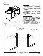
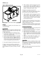
DIGITAL TIMER (Late Models)

BLU/BLK wire from TL5 to P1
WHI/GRN wire from TL4 to (RED) Pump
WHI/BLU wire from TL3 to Swing Arm Switch
WHI wire from TL2 to P2
BLK wire from TL1 to P3

J2 - Three Pin connector from Half/Full Batch
Switch

P2037

FIG. 30 DIGITAL TIMER TERMINALS

1.

Modifying brew volumes. 

To modify a brew vol-

ume, first check that the SET/LOCK switch is in the
“SET” position on the circuit board.

To  increase a brew volume, 

place the ON/OFF

switch in the “ON” position, press and hold the START
switch until you see three breaks in the water stream
from the swing arm. Release the switch and press it
again one or more times. (Failure to release the switch
within two seconds after the third break in the water
stream causes the volume setting to be aborted and
previous volume setting will remain in memory.) Each
time the switch is pressed, two seconds are added to
the brew time period. Allow the brew cycle to finish in
order to verify that the desired volume has been
achieved.

To decrease a brew volume, 

place the ON/OFF

switch in the “ON” position, press and release the
START switch once for every two-second interval to
be removed from the total brew time period; then im-
mediately press and hold down the START switch until
you see three breaks in the water stream from the
swing arm. Release the switch. (Failure to release the
switch within two seconds after the third break in the
water stream causes the volume setting to be aborted
and previous volume setting will remain in memory).
Allow the brew cycle to finish in order to verify that
the desired volume has been achieved.

2.

Setting brew volumes.  

To  set a brew volume,

first check that the SET/LOCK switch is in the “SET”
position on the circuit board. Place the ON/OFF switch
in the “ON” position, press and hold the START switch
until you see three breaks in the water stream from
the swing arm and then release the switch. (Failure to
release the switch within two seconds after the third
break in the water stream causes the volume setting
to be aborted and previous volume setting will remain
in memory.)
View the level of the liquid being dispensed. When
the desired level is reached, turn the ON/OFF switch

to “OFF”.

NOTE: 

 The brewer remembers this volume and will

continue to brew batches of this size until the volume
setting procedure is repeated.

NOTE: 

When brewing coffee, volume will decrease due

to absorption by the coffee grounds.

NOTE: 

Half-Batch and full batch settings must each

be set separately.

3.

Setting programming disable feature. 

If it be-

comes necessary to prevent anyone from changing
brew time once programmed, you can set the SET/
LOCK switch to the “LOCK” position. This will pre-
vent any further programming until switch is once
again put into the “SET” position.

10060.3  070102

Summary of Contents for U3A

Page 1: ...NG SERVICE MANUAL BUNN O MATIC CORPORATION POST OFFICE BOX 3227 SPRINGFIELD ILLINOIS 62708 3227 PHONE 217 529 6601 FAX 217 529 6644 www bunnomatic com U3A BUNN 10060 0003A 07 02 2002 Bunn O Matic Corp...

Page 2: ...ted by BUNN shipping the defective equipment prepaid to an authorized BUNN service location and 3 receiving prior authorization from BUNN that the defective equipment is under warranty THE FOREGOING W...

Page 3: ...ewer and in this manual They were written for your protection All notices on the brewer are to be kept in good condition Replace any unreadable or damaged labels 00878 0000 12593 0000 03408 0000 03409...

Page 4: ...cold water system with operating pressure between 20 and 90 psi 138 and 620 kPa from a 1 2 or larger supply line A shut off valve should be installed in the line before the brewer Install a regulator...

Page 5: ...nect the brewer to the power source and wait for the water in the tank to heat to the proper temperature This will take approximately 1 2 hours depending on the incoming water temperature Some water w...

Page 6: ...the water stream from the swing arm Release the switch Failure to release the switch within two seconds after the third break in the water stream causes the volume setting to be aborted and previous v...

Page 7: ...damp cloth 2 Drain both coffee reservoirs by opening coffee faucets When empty close faucets 3 Cycle two or three inches of water into each coffee reservoir adding a bucket of crushed ice to obtain a...

Page 8: ...airofelectricalequipmentshouldbeperformedonlybyqualifiedservicepersonnel All electronic components have 230 volt ac and low voltage dc potential on their terminals Shorting of terminals or the applica...

Page 9: ...ng procedures See page 20 Refer to Service Solenoid Valve for testing procedures See page 22 A Direction of flow arrow must be pointing towards brewer B Remove the strainer and check for obstructions...

Page 10: ...r must be level and installed on a sturdy structure Refer to Service Solenoid Valve for testing procedures See page 22 Refer to Service Liquid Level Board for testing procedures See page 17 Refer to S...

Page 11: ...rtoService Timerfortesting procedures See page 26 or 28 Refer to Service Start Switch for testing procedures See page 23 RefertoService Timerfortesting procedures See page 26 or 28 Refer to Service So...

Page 12: ...to Service Timer for test ing procedures See page 26 or 28 Checkpumpflowratewithawatch Pumpflowrateshouldbeapproxi mately 24 ounces in 15 seconds Be sure pump assembly is free of any obstructions Plum...

Page 13: ...tthebrewerfromthepower source before the removal of any panel or the replace ment of any component All components are accessible by the removal of the swing spout front cupola cover rear cupola cover...

Page 14: ...ce If voltage is present as described proceed to 9 If voltage is not present as described refer to the wiring diagrams and check the brewer wiring harness 9 Check for continuity across the terminals o...

Page 15: ...hermostat Removal and Replacement 1 Disconnect the wires from the control thermostat 2 Remove the thermostat capillary bulb by firmly pullinguponthecapillaryatthecomponentbracket This will disengage t...

Page 16: ...178 60 RED from ON OFF Switch P2112 RED from Main Harness FUSE AND FUSE HOLDER Removal and Replacement Fuse 1 Remove the cap from the fuse holder 2 Remove fuse from the fuse holder inspect if blown di...

Page 17: ...EVEL BOARD AND LEVEL PROBE P2178 55 Location The liquid level board is located on the left rear of the component bracket The level probe is located on the right rear of the component bracket Test Proc...

Page 18: ...by touching the end of the probe to any metal surace of the brewer Measure the voltage be tween T1 and T3 on the liquid level board The voltage should be 0 volts with the probe touching the frame and...

Page 19: ...agram and check the brewer wiring harness 5 Disconnect all wires on the ON OFF switch 6 Check for continuity across the center terminal 2 andthelowerterminal 1 whentheswitchisinthe ON upper position C...

Page 20: ...pump does not run replace the pump If voltage is not present as described refer to the wiring diagram and check the brewer wiring harness Removal and Replacement Refer to Fig 15 1 Disconnect the wire...

Page 21: ...must not present when the switch is in the OPEN right full position If continuity is present as described the switch is operating properly If continuity is not present as described replace the switch...

Page 22: ...ribed reconnect the wires to the solenoid If continuity is not present as described replace the solenoid valve 7 Check the solenoid valve for coil action Connect thedispensertothepowersource Listencar...

Page 23: ...when the switch is in the upper position If continuity is present as described reconnect the wires the switch is operating properly If continuity is not present as described replace the switch BLU to...

Page 24: ...operating properly If continuity is not present as described replace the switch Removal and Replacement NOTE Measurethedistancefromthetopoftheswitch plunger to the hood cover The same distance is nee...

Page 25: ...he brewer from the power source 2 Disconnect the wires from each tank heater 3 Check for continuity across the terminals of each tank heater If continuity is present as described tank heaters are oper...

Page 26: ...he component bracket Test Procedures 1 Disconnect the brewer from the power source 2 Disconnectthepolarized threepinconnectorfrom the brewer main harness and rotate the brew timer dial fully countercl...

Page 27: ...uired If voltage is not present as described replace the timer Removal and Replacement 1 Separate all connectors between the brewer wir ing harness and the timer 2 Disconnect the timer leads from the...

Page 28: ...scribed disconnect the brewer from the power source and replace the timer 7 With a voltmeter check the voltage across termi nals TL1 and TL4 when the ON OFF switch is in the ON position Connectthebrew...

Page 29: ...stream from the swing arm Release the switch Failure to release the switch within two seconds after the third break in the water stream causes the volume setting to be aborted and previous volume sett...

Page 30: ...Page 30 10493 0004A 07 02 2002 BUNN O MATIC CORPORATION 10060 3 070102...

Reviews: