Bunn H5M Operating & Service Manual Download Page 4

4

ELECTRICAL REQUIREMENTS

CAUTION

 - The dispenser must be disconnected from the power source until specified in Initial Set-Up.

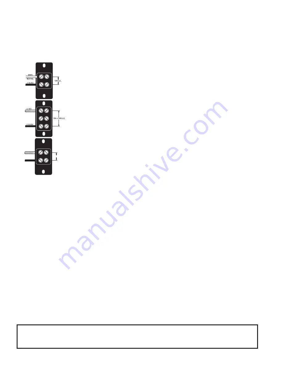
The H5M dispenser requires 2-wire, grounded service rated 120, 208, or 240 volts ac, 20 amp, single phase.

The H5MA, 230V-CE dispenser requires 2-wire, grounded service rated 230 volts ac, 40 amp, single phase, 50/60Hz. (Refer 

to the dispenser’s dataplate for exact voltage requirement.)

Electrical Hook-Up


CAUTION –

 Improper electrical installation will damage electronic components.


1.  An electrician must provide electrical service as specified.


2.  Using a voltmeter, check the voltage and color coding of each conductor at the electri-

cal source.


3.  Remove the upper and lower rear panels. Turn the knob of the thermostat to the “OFF” 

position (fully counterclockwise).


4.  Install a strain relief and the proper electrical wiring to the terminal block.


5.  Connect the dispenser to the power source and verify the voltage at the terminal block 

before proceeding.  Reinstall both rear panels.


6.  If plumbing is to be hooked-up later be sure the dispenser is disconnected from the 

power source. If Plumbing has been hooked-up, the dispenser is ready for Initial 

Set-Up.

10267 040709

PLUMBING REQUIREMENTS

This dispenser must be connected to a 

COLD WATER 

system with operating pressure between 20 and 90 psi  (138 and 

620 kPa)from a 

1

⁄2” or larger supply line. A shut-off valve should be installed in the line before the dispenser. Install a 

regulator in the line when pressure is greater than 90 psi (620 kPa) to reduce it to 50 psi (345 kPa). The water inlet fitting 

is 

1

⁄4” flare.

NOTE -

 Bunn-O-Matic recommends 

1

⁄4” tubing for installations of less than 25 feet and 

3

⁄8” for more than 25 feet from the 

1

⁄2” water supply line. At least 18 inches of an FDA approved flexible beverage tubing, such as reinforced braided polyethylene 

or silicone, before the dispenser will facilitate movement to clean the countertop. Bunn-O-Matic does not recommend the 

use of a saddle valve to install the dispenser. The size and shape of the hole made in the supply line by this type of device 

may restrict water flow.

CE REQUIREMENTS

• This appliance must be installed in locations where it can be overseen by trained personnel.

• For proper operation, this appliance must be installed where the temperature is between 5°C to 35°C.

• Appliance shall not be tilted more than 10° for safe operation.

• An electrician must provide electrical service as specified in conformance with all local and national codes

• This appliance must not be cleaned by water jet.

• This appliance is not intended for use by persons (including children) with reduced physical, sensory or mental capa-

bilities, or lack of experience and knowledge, unless they have been given instructions concerning use of this appli-

ance by a person responsible for its safety.


Children should be supervised to ensure they do not play with the appliance.


If the power cord is ever damaged, it must be replaced by the manufacturer or authorized service personnel with a special 

cord available from the manufacturer or its authorized service personnel in order to avoid a hazard.

L2 RED 

L1 BLACK 

230V A.C.

This equipment must be installed to comply with the International Plumbing Code of the International 

Code Council and the Food Code Manual of the Food and Drug Administration (FDA).  For models installed 

outside the U.S.A., you must comply with the applicable Plumbing/Sanitation Code for your area.

Summary of Contents for H5M

Page 1: ...vision of the Operating Manual or to view the Illustrated Parts Catalog Programming Manual or Service Manual please visit the Bunn O Matic website at www bunn com This is absolutely FREE and the quickest way to obtain the latest catalog and manual updates For Technical Service contact Bunn O Matic Corporation at 1 800 286 6070 10267 0000G 04 09 1988 Bunn O Matic Corporation ...

Page 2: ...ccordingly statements by such individuals whether oral or written do not constitute warranties and should not be relied upon If BUNN determines in its sole discretion that the equipment does not conform to the warranty BUNN at its exclusive option while the equipment is under warranty shall either 1 provide at no charge replacement parts and or labor during the applicable parts and labor warranty ...

Page 3: ...ust be installed to comply with the International Plumbing Code of the International Code Council and the Food Code Manual of the Food and Drug Adminis tration FDA For models installed outside the U S A comply with the applicable Plumbing Sanitation Code WARNING Fill water tank before turning on thermostat or connecting appliance to power source Use only on a properly protected circuit capable of ...

Page 4: ...ends 1 4 tubing for installations of less than 25 feet and 3 8 for more than 25 feet from the 1 2 watersupplyline Atleast18inchesofanFDAapprovedflexiblebeveragetubing suchasreinforcedbraidedpolyethylene or silicone before the dispenser will facilitate movement to clean the countertop Bunn O Matic does not recommend the use of a saddle valve to install the dispenser The size and shape of the hole m...

Page 5: ...TION The dispenser must be disconnected from the power source throughout these steps 1 Disconnect the dispenser from the power source 2 Shut off and disconnect the incoming water supply 3 Remove the 4 40 screws at the sides of the top panel 4 Gently remove one of the grommets from the tank lid 5 Insert a tube to the bottom of the tank and syphon ALL of the water out Bunn O Matic has a syphon assem...

Page 6: ... a supply of water The use of two wrenches is recommended whenever plumbing fittings are tightened or loosened This will help to avoid twists and kinks in the tubing Make certain that all plumbing connections are sealed and electrical connections tight and isolated This dispenser is heated at all times Keep away from combustibles WARNING Exercise extreme caution when servicing electrical equipment...

Page 7: ...ner flow control and check for obstructions Clear or replace Refer to Service safety overflow switch for testing procedures See page 11 Refer to Service liquid level board for testing procedures See page 15 Refer to Service solenoid valve for test ing procedures See page 12 Refer to Service solenoid valve for test ing procedures See page 12 Refer to Service liquid level board for testing procedure...

Page 8: ...n top of the solenoid valve must be tight or it will vibrate during operation Plumbing lines should not be resting on the counter top A The dispenser must be connected to a cold water line B Water pressure to the dispenser must not be higher than 90 psi 620 kPa Install a regulator if necessary to lower the work ing pressure to approximately 50 psi 345 kPa Refer to Service control thermostat for te...

Page 9: ...ctrical equipmentshouldbeperformedonlybyqualifiedservice personnel Disconnect the dispenser from the power source when servicing except when electrical tests are required and the test procedure specifically states to connect the dispenser to the power source Contactor 17 Limit Thermostat 10 Liquid Level Board 15 Safety Overflow Switch 11 Solenoid Valve 12 Tank Heater 13 Control Thermostat 14 The c...

Page 10: ...e with two 10 32 nuts 4 Refer to FIG 2 when reconnecting the wires Test Procedure 1 Disconnect the dispenser from the power source 2 Remove the blue black wire at the limit thermostat coming from the control thermostat 3 Check the voltage across the blue black wire and the black wire at the tank heater with a voltmeter Connect the dispenser to the power source The indication must be a 100 to 120 v...

Page 11: ...bed replace the safety overflow switch FIG 3 SAFETY OVERFLOW SWITCH FIG 4 SAFETY OVERFLOW WIRING RED to BLK Wire from Terminal Block RED to BLK Wire from Liquid Level Board 2 P1793 P1777 Removal and Replacement 1 Disconnect the black wires from the safety overflow switch 2 Remove the nut beneath the copper overflow cup 3 Remove the entire switch assembly from the cup 4 Place the new switch assembl...

Page 12: ...ng bracket 7 Securely install the new solenoid valve to its mount ing bracket The direction of flow arrow must be pointing towards the tank lid 8 Attach the solenoid valve and mounting bracket to the component bracket 9 Securely fasten the water lines to and from the solenoid valve 10 Reconnect the wires FIG 6 Test Procedure 1 Disconnect the dispenser from the power source and turn off the water s...

Page 13: ...RING BLK to Limit Thermostat or BLK to Contactor WHI to Terminal Block or RED to Contactor P1780 P1793 4 Remove the tank heater from the tank lid and in spect it for cracks in the sheath If the sheath shows no sign of damage proceed to 5 If the sheath is damaged replace the tank heater 5 Check for continuity across the tank heater termi nals If continuity is present as described reinstall the tank...

Page 14: ...er mostat is turned ON fully clockwise Connect the dispenser to the power source The indication must be as described in step 2 Voltage must not be indicated when the thermostat is turned OFF fully counterclockwise 5 Disconnect the dispenser from the power source P1781 If voltage is present as described the thermostat is operating properly If voltage is not present as described replace the thermost...

Page 15: ...be a 100 to 120 volts ac for 100 to 120 volt mod els b 200 to 240 volts ac for 200 to 240 volt mod els c 230 volts ac for 230 volt models after a delay of approximately 5 seconds 8 Touch the free end of jumper wire to the dispenser housing The indication must be 0 9 Move the jumper wire away from the dispenser housing The indication must again be a 100 to 120 volts ac for 100 to 120 volt mod els b...

Page 16: ...e level control board and level probe are operating properly If voltage is not present as described check the pink probe wire SERVICE cont Liquid Level Board cont FIG 12 LIQUID LEVEL BOARD WIRING BLU to Solenoid T 1 BLK to Overflow Safety Switch T 2 WHI to Terminal Block T 3 PNK to Level Probe T 4 P1784 Removal and Replacement 1 Remove all wires from the level control board 2 Remove two 8 32 screw...

Page 17: ...uity is not present as described replace the contactor 6 Check the voltage across the upper left terminal and the upper right terminal on the contactor with a voltmeter Connect the dispenser to the power source The indication must be a 240 volts ac for 240 volt models b 230 volts ac for 230 volt models 7 Disconnect the dispenser from the power source If voltage is present as described proceed to 8...

Page 18: ...Replacement 1 Disconnect all the wires from the contactor 2 Remove the two 8 32 screws securing the con tactor to the contactor mounting bracket remove contactor and protective shield Discard contac tor SERVICE cont Contactor cont 3 Install new contactor with shield between mounting bracket and contactor and secure with two 8 32 screws 4 Refer to Fig 14 and reconnect the wires 10267 011599 ...

Page 19: ...MOSTAT GRN BLK L1 N BLK WHI MAIN ON OFF SWITCH Late Models only 4 3 1 2 LIQUID LEVEL BOARD BLK BLK BLK BLK SW THERMOSTAT 10262 0000D 01 07 1987 BUNN O MATIC CORPORATION SCHEMATIC WIRING DIAGRAM H5M BLK SOL GREEN BLU BLK BLK PROBE P N K RED RED RED BLU BLK BLK BLK RED RED BLK N O N O K RED RED RED TANK HEATER 208 or 240 VOLTS A C 2 WIRE GND SINGLE PHASE OPTIONAL READY INDICATOR OVERFLOW PROTECTION ...

Page 20: ... BUNN O MATIC CORPORATION SCHEMATIC WIRING DIAGRAM H5MA 230V CE L1 L2 SOL GREEN BLU BLK BLK PROBE P N K RED RED RED BLU BLK BLK RED 12 BLK 12 N O N O K RED RED RED TANK HEATER 230 VOLTS A C 2 WIRE SINGLE PHASE OVERFLOW PROTECTION SWITCH N C LIMIT THERMOSTAT LIMIT THERMOSTAT 10267 040709 ...

Reviews: