Technical Data
9
2.4
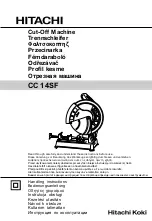
Pin assignment
Pin type:
AMP 14-pole, pins
1
4
8
12
3
7
11
14
Figure 2.4/1: Pin assignment
Pin
Color
Function
1
brown
Heater Hand unit (N)
2
free
3
blue
Heater Hand unit (L1)
4
grey
Sensor hand unit (Pt100)
5
green/yellow
Protective Earth (PE)
6
grey
Sensor hand unit (Pt100)
7
free
8
free
9
free
10
free
11
black
Sensor hose (Pt100)
12
black
Sensor hose (Pt100)
13
yellow
Heater hose (L1)
14
violet
Heater hose (N)
Summary of Contents for HB 5010
Page 10: ...2...
Page 14: ...Special security advice 6...
Page 16: ...Technical data 8 Figure 2 1 2 Location of type plate on the inside of the unit...
Page 28: ...Operation 20...
Page 40: ...Operation 32...
Page 57: ...Repairs 49...
Page 60: ......
Page 62: ...Table of Contents 4 Table of contents...
Page 64: ...Specific security advice 6...
Page 68: ...Technical Data 10...
Page 76: ...Maintenance 18...
Page 80: ......
Page 82: ...4 Inhaltsverzeichnis...
Page 84: ...Specific safety instructions 6...
Page 90: ...Construction and function 12...
Page 92: ...Technical data 14...
Page 104: ...What happens if 26...
Page 107: ...Accessories 29...
Page 110: ...Ersatzteillisten...
Page 115: ...Spare parts list 3 1 HB 5010 Tank System basic unit Fig 1 1 Spare parts for basic unit Part 1...
Page 128: ...Spare parts list 16 2 3 Spare parts bead and spray 19 9 Fig 2 11 Grip casing both versions...
Page 129: ...Spare parts list 17 11 Fig 2 12 Heat insulation half shell both versions...
Page 130: ...18 Spare parts list 10 Fig 2 13 Trigger and mounting parts both versions...
Page 133: ...Table of contents 21...
Page 136: ...Table of Contents 2...
Page 138: ...4...