background image

Operation 


62 

SnackFix 

 2016-08 


7.4.2 

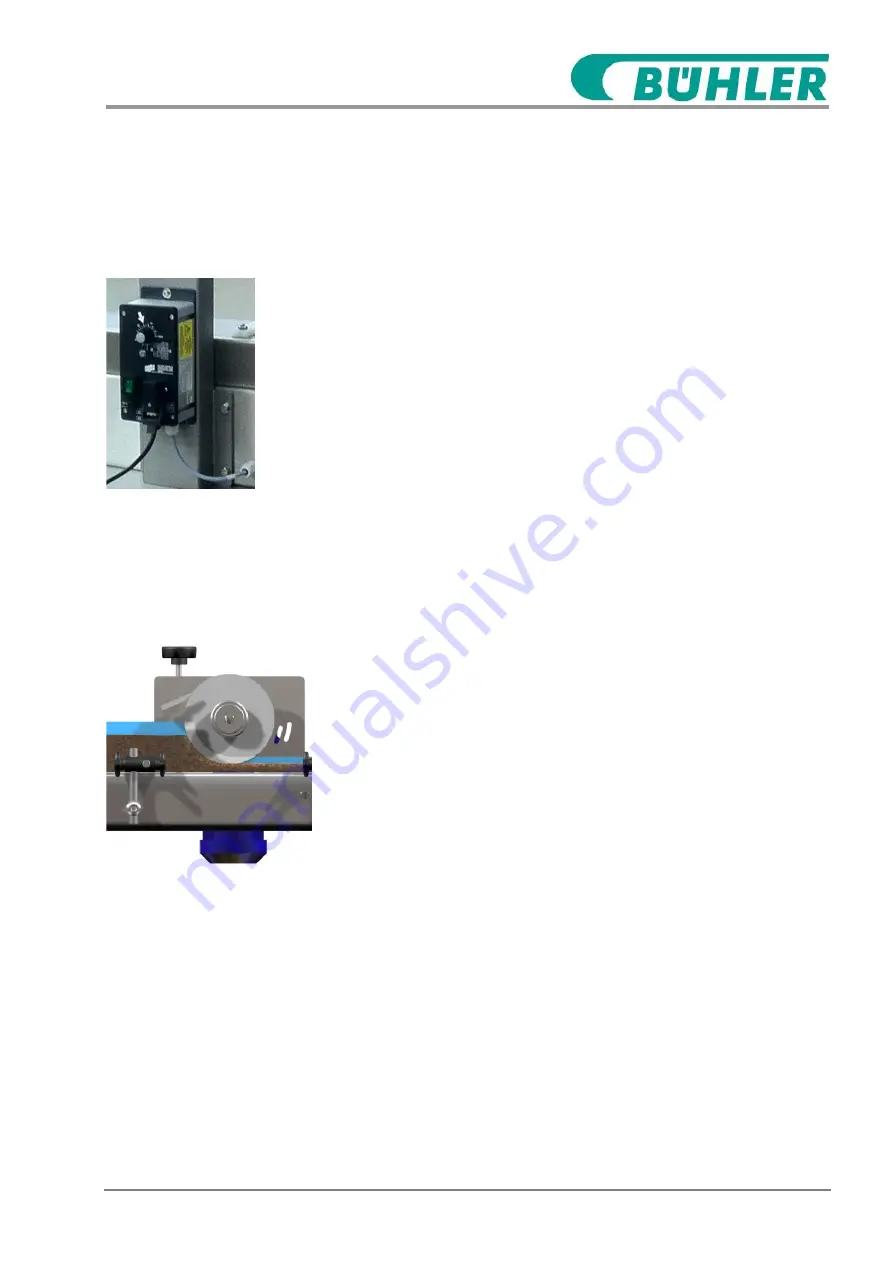
Adusting the vibration unit 

The amount of cereals (kg/min) depends of the creal mix and the in-
tensity of the vibration. The correct flowrate has to be found out via 

measurement. Use a scale and set the correct vibration speed. 


Fig. : Adjustment vibration 


Adjusting the vibration 

1.


Turn left 

– less cereals. Turn right – more cereals. 


7.4.3 

Adjusting the working position at the EGW 

Lifting and lowering devices for adjusting the working positions are 

located on the equalizing rollers EGW. 


Fig. 4: Lifting and lowering device on 
the EGW 


Adjusting the working position 

1.


Turn the hand crank and adjust the required height. Use the 

thickness gauge (accessories). 


Summary of Contents for 63911

Page 1: ...Operating Instructions SnackFix Issue date 2016 08 V1 0 Translation of original document German German version is binding Read the instructions carefully prior to any installations...

Page 2: ...2 SnackFix 2016 08 B hler GmbH Daimlerstrasse 8 74211 Leingarten Germany T 49 7131 907 0 F 49 7131 907 301 info countlines buhlergroup com buhlergroup com countlines B hler GmbH 2016...

Page 3: ...d from any potential deviations Besides this manual the manuals of the installed components shall apply that can be found in the annex Liability limitations All information and notices in this manual...

Page 4: ...luding excerpts as well as the exploitation and or conveyance of the content without writ ten authorization of the manufacturer is not permitted with the excep tion of the use for internal purposes Vi...

Page 5: ...hazards at the work station 20 2 6 2 Hazards from electric powers 21 2 6 3 Hazards from mechanics 22 2 6 4 Hazards from lacking hygiene 23 2 6 5 Hazards from high temperatures 24 2 6 6 Hazards from n...

Page 6: ...ransport inspection 54 5 4 Transport 54 5 5 Packaging 56 5 6 Storage 57 6 Installation and First Start Up 58 6 1 Safety 58 6 2 Requirements at the Installation Site 58 7 Operation 59 7 1 Safety 59 7 2...

Page 7: ...lfunctions 94 10 1 Safety 94 10 2 Behavior in Case of Malfunction 97 10 3 Malfunction signal 97 10 5 Malfunction Chart 98 10 5 1 Cutting unit 98 10 5 2 Equalizing roller EGW 180 100 99 10 6 Measures a...

Page 8: ...r 40l 4 Vibration feeder 5 Contimix 6 Conveyor belt I TB 7 Equalizing Roller I EGW 180 8 Equalizing Roller II EGW 180 9 Conveyor belt I TB 10 Cutting machine SZ 100 M TB 11 12 Control cabinet preparat...

Page 9: ...16 08 9 1 2 Short description Detailed description Chapter Design and Function on page 41 The line serves for producing confectionery products such as granola bars on a small scale For this the ingred...

Page 10: ...10 SnackFix 2016 08 1 3 Other applicable documents In addition to this instruction following documents are applicable Operating instructions of the control panels Operator manual Instructions of integ...

Page 11: ...e the safety instructions must be complied with and carefully carried out DANGER This combination of a symbol and signal word indicates an imme diate hazardous situation which could lead to death or s...

Page 12: ...ces and other elements the following symbols and highlighting are used in the text 1 Identifies step by step instructions Identifies a condition or an automatic sequence as a result of an action Ident...

Page 13: ...use that exceeds or differs from the intended use is regarded as misuse WARNING Danger from misuse Misusing the machine can lead to dangerous situations Do not use the machine in explosive atmospheres...

Page 14: ...rator must check to see if the operating instructions he she prepared correspond to the current status of the regula tions during the machine s entire operating time and if neces sary adjust them The...

Page 15: ...k environment in which he she works and recognizes the relevant standards and regulations The electrician must comply with the regulations and conditions of the currently valid legal guidelines on acc...

Page 16: ...rements de scribed here do not know the hazards in the workshop area For this reason there is a possibility of serious injury or death for this unauthorized individual Keep unauthorized individuals aw...

Page 17: ...food industry PSA_Allg 2 5 Personal safety gear Personal safety gear is used to protect employees against hazards which could affect their safety or health when working When carrying out the various...

Page 18: ..._Kleid Hygienic protective clothing Hygienic protective clothing is tight fitting work clothes with low tearing strength with close fitted sleeves and without any protruding parts It is used to protec...

Page 19: ...ve gloves Hygienic protective gloves serve for adhering to the hygiene require ments and for protecting the hands from friction abrasion cuts or deeper injuries as well as from contact with hot surfac...

Page 20: ...m dangerous sit uations pay attention to the safety advices given in the present sec tion and in any other chapters in this instruction 2 6 1 General hazards at the work station AllG_1_Schmutz Dirt an...

Page 21: ...to off or disconnect from mains and secure this status for the duration of the work on the electrical system and equipment Never bypass or disable fuses When changing fuses use the correct amperage K...

Page 22: ...at no components are still moving Wear close fitting protective clothing in the hazard zone with low tear strength Mech_2_Band Conveyor belts and deflection rollers WARNING Risk of crushing and catchi...

Page 23: ...tion make sure that the machine stands stable and does not reel Put on the brakes of the wheels 2 6 4 Hazards from lacking hygiene Hyg_1_Grund Basics of hygiene WARNING Danger of injury from contamina...

Page 24: ...t surfaces Before starting any work make sure that all surfaces have cooled down to the ambient temperature Hot operating materials CAUTION Danger of scalding from hot operating materials Operating ma...

Page 25: ...ues above 80 dB A always wear hearing protection Only stay in danger zone when absolutely necessary 2 7 Safety installations Allg_0_SiEin WARNING Danger to life from non functioning safety equipment W...

Page 26: ...Safety installations 1 Main switch on the control cabinet of the Mass preparation unit 2 Main switch on the control cabinet of the cutting unit 3 Emergency stop button 4 Touch Panel on off 5 Solenoid...

Page 27: ...the emergency stop has been cleared and all safety devices are installed and functioning Do not turn the main switch to position I before any dangers are eliminated Emergency stop button Fig 4 Emergen...

Page 28: ...Solenoid safety switch protec tive hoods Fig 5 Solenoid safety switch at the hoods The protective hood of the cutting machine is equipped with solenoid safety switch 1 The machine stops as soon as the...

Page 29: ...s turn the main switch to the 0 position 2 Secure the main switch with a lock 3 Give the key to the lock to a responsible employee for safekeep ing Restarting 1 After all work has been done make sure...

Page 30: ...Safety Secure against restarting 30 SnackFix 2016 08 The main switches are located at the control cabinets of the mass preparation unit and the cutting unit...

Page 31: ...d measures 4 Alert the fire brigade and or emergency medical services 5 Inform the persons in charge on site 6 Switch the machine off and secure against restarting 7 Clear the way for rescue vehicles...

Page 32: ...easily readable condition Replace damaged signs or labels immediately The following symbols and note signs can be located in the working area Electric hazard Only electricians are allowed to work in...

Page 33: ...rt belt Hot Surface Component surfaces can heat up greatly during operation Skin contact with hot surfaces causes serious burns Do not touch hot surfaces Always wear heat resistant protective clothing...

Page 34: ...r Hauptschalter in Nullstellung ist Entladezeit abwarten Attention Only when the main switch is in off position the frequency converter is without voltage Wait for discharge time Attention Only when t...

Page 35: ...w on the handling of environmentally harmful substances and their disposal are to be observed at all times If environmentally harmful substances accidently get into the environment immediately take ap...

Page 36: ...alue Serial number 63911 Serial number preparation unit 63911 01 Serial number Equalizing roller EGW I 180 100 63911 02 Serial number Equalizing roller EGW II 180 100 63911 03 Serial number Cutting ma...

Page 37: ...ntation file Specification Value Unit Length approx 3000 mm Width approx 800 mm Height approx 1600 mm Working height approx 900 mm Working direction from left to right Nominal width for forming approx...

Page 38: ...Hz Connection power 10 kVA Current consumption maximum 15 A Fuse protection 25 A Control voltage 24 V DC Protection class IP 54 Specification Value Unit Voltage 3 x 400 V AC Frequency 50 Hz Connection...

Page 39: ...pecification Value Unit Operating speed 0 8 2 4 m min Power of all drives see 62329 MSR 3 5 Operating Conditions Specification Value Unit Temperature range 10 30 C Relative humidity maximum 60 3 6 Noi...

Page 40: ...nstruction Name plates control cabinets Fig 8 Control cabinet name plate Further name plates are located in the control cabinets of the following machines Mass preparation unit Equalizing rollers 2 pi...

Page 41: ...ported via the vibration unit into the contimix The pump is dosing the Binder into the contimix Cerals and Binder are gently mixed and transported to the first con veyor The transport belt conveys the...

Page 42: ...in the documentation file for further information 4 2 2 Pump Please see the separate documentation Pump in the documentation file for further information 4 2 3 Mass preparation unit Fig 9 Mass prepara...

Page 43: ...43 4 2 3 1 Vibration feeder The vibration feeder conveys the cereals from the hopper to the con timix With the control unit on the back side of the machine it is possi ble to change the flowrate kg h...

Page 44: ...ng roller is mounted on the transport belt The equalizing roller evens the surface of the mass slab and cali brates the slab height The height of the equalizing roller can be adjusted with a spindle T...

Page 45: ...ged belt edge 6 Drawer 7 Drive motor for transport belt 8 Machine foot 9 Rolls 10 Belt clamping device Different parameters such as the belt speed can be adjusted at the control panel which is install...

Page 46: ...ps as soon as the protective cap is opened Fig 13 Cutting device 1 Knife 2 Downholder with scraper 3 4 Depending on the product to be processed the machine can be oper ated with a conventional cutting...

Page 47: ...ble in height There are two angles 1 on the bottom side The downholder should be adjusted approx 2 3 mm higher than the product which is to be cut Two scrapers 2 are installed at the downholder The sc...

Page 48: ...the belt surface Displays and Controls 4 2 6 Control Panels The following machines are equipped with control panels Mass preparation unit Cutting unit Fig 16 Control panel 1 Display 2 Emergency stop b...

Page 49: ...kFix 2016 08 49 4 2 7 Operating elements The following components are equipped with main switches Mass preparation unit Cutting unit Fig 17 Main switches 1 Main switch at the Mass preparation unit 2 M...

Page 50: ...re that the cause for the emergency stop has been eliminated and that all safety equipment is mount ed and fully functional Only release the emergency stop button when no further hazard is present 1 R...

Page 51: ...onnection for power supply The connection for power supply is connected via the control cabinets by customer 4 4 Workplace The workplace of the operating personnel is located at the operating side of...

Page 52: ...ions on the packaging Only use the designated lifting points Remove packaging first shortly before assembly Suspended loads WARNING Danger to life by suspended loads During lifting of loads danger to...

Page 53: ...ng 5 2 Symbols on the packaging The following symbols are on the packaging Observe the symbols during transport Centre of gravity Identifies the centre of gravity of the packaging Observe the centre o...

Page 54: ...ity period 5 4 Transport Transport of pallets with the forklift Transport pieces which are mounted to pallets can be transported with a forklift under the following conditions The forklift must be des...

Page 55: ...to the adjacent drawing 2 Make sure that the transport piece is suspended leveled observe centre of gravity 3 Start the transport Transport of pallets with the crane Transport pieces which are mounte...

Page 56: ...ging and only re move it first shortly before the assembly Dispose of packaging material according to the respective valid legal regulations and local rules NOTICE Danger to the environment from impro...

Page 57: ...chanical bumping or shaking Storage temperature 15 to 35 C 59 to 95 F Relative humidity max 60 When storing for more than 3 months check the general condi tion of all pieces and the packaging If neces...

Page 58: ...start up unauthorized Consult the manufacturer also in case of later relocations 6 2 Requirements at the Installation Site The following conditions must be fulfilled The installation site is flat and...

Page 59: ...ly no individuals are in the hazard zone Never bypass or disable the safety equipment during operation of the machine Mech_2_Band Conveyor belts and deflection rollers WARNING Risk of crushing and cat...

Page 60: ...button 2 If your own health is not endangered rescue other persons from the danger area 3 If required start first aid measures 4 Alert the fire brigade and or emergency medical services 5 Inform the p...

Page 61: ...nic protective cap Hygienic protective clothes Safety shoes 7 4 1 Set Up Vessel HM520 Fig 22 level gauge 1 Fill the water jacket between the two lines on the level gauge 2 Set temperature at 85 C Fig...

Page 62: ...rect vibration speed Fig Adjustment vibration Adjusting the vibration 1 Turn left less cereals Turn right more cereals 7 4 3 Adjusting the working position at the EGW Lifting and lowering devices for...

Page 63: ...mass characteristics and is to be determined in trials Adjust scraper The scraper can be fitted either in front of or behind the roller 1 Loosen the screws 1 2 Adjust the distance between scraper 2 an...

Page 64: ...ose Turn on the belt drive if the belt is running in the middle for at least 1min Fig Belt adjusting and belt tensioning Adjusting the working position 1 Turn the adusting screws 1 and monitor if the...

Page 65: ...or the hexagon screw 3 up NOTICE Damages to property during contact of the knives with the conveyor or the counter cutting ledge In case of incorrect adjustment the belts and the counter cutting ledge...

Page 66: ...enic protective cap Hygienic protective clothes Safety shoes Adjusting height of downholder Fig 26 Downholder 1 Cylinder head screw 2 Scraper 3 Downholder angle 4 Knife 1 Switch the machine off and se...

Page 67: ...Operation SnackFix 2016 08 67 The scrapers 2 must uniformly push at both sides of the knife 6 Tighten the cylinder head screw 1 7 Close protective cover...

Page 68: ...ition of the bolts 1 Switch the machine off and secure against restarting Fig 27 Plug in position bolts 2 Demount encasement at the drive side 3 Loosen screw S and pull out bolt B 4 Plug bolts B into...

Page 69: ...9 7 6 Actions after usage Trained employee Clean the machine 1 Switch the machine off and secure against restarting 2 Clean the machine after every use 3 For longer shutdowns make sure that the machin...

Page 70: ...serious injury or death Before beginning work switch off the electrical power supply and secure against restarting Elekt_2_Rest Stored charges DANGER Electrocution danger from stored charges In elect...

Page 71: ...rting any work make sure that all surfaces have cooled down to the ambient temperature Mech_1_Bewegt Moving components WARNING Danger of injury from moving components Rotating and or components moving...

Page 72: ...y and health protection Follow all directions relevant to hygiene in this manual Make sure that the operating environment complies with the specifications listed for the machine at all times Elekt_5_S...

Page 73: ...and comply with screw tight ening torque Observe the following before restarting Make sure that all maintenance work is carried out and completed according to the information and directions in this m...

Page 74: ...yee Check hoses for damages and leaks After every use Clean the machine Trained employee Perform a visual check for damages and leaks Daily Visual control scrapers Wear corrosion adjustment and functi...

Page 75: ...chnical employee When required Change scrapers on the downholder Technical employee Change knives Fill up release agent When required Inspection Transport belts Check roller scrapers and belt scrapers...

Page 76: ...ing protection Company ECOLAB P3 topax 17 foam cleaning P3 topax 990 foam disinfection Please see the data sheets in the documentation folder for specifications WARNING Danger of injury from hot surfa...

Page 77: ...eps Pre flushing 1 Pre flush the parts that are to be cleaned with water 40 50 C 104 122 F Foam cleaning 2 Foam the parts with foam cleaner concentration 2 3 3 Leave the cleaning agent on for approx 1...

Page 78: ...ater through vessel hoses and pump until water is clean Pump WARNING Danger of injury from running pump Gear inside Always weause hoses while running the pump 3 Close outlet of the conimix and flush w...

Page 79: ...Maintenance Maintenance Plan SnackFix 2016 08 79 Fig 28 Cutting unit 1 Front plate Contimix 2 Screws When mounting the screws be sure that the screws have space to each other 1 min 15mm 2...

Page 80: ...ice WARNING Danger of injury from sharp edges at the knife and the scrapers Sharp edges can cause severe cuts Always wear protective gloves when working at sharp edges 3 Open protective cover 4 Remove...

Page 81: ...Belt drive roll 5 Safety cover 6 Tensioning roll 9 Release belt 6 10 Remove scraper and clean it 11 Clean surface and bottom side of the belt 3 12 Clean belt drive roll 4 belt tensioning roll 6 13 Aft...

Page 82: ...Fix 2016 08 It is possible to remove the short transfer belt without any tools Plug off the motor and lift the belt sligthtly up and pull NOTICE Belts must be tensioned parallel If not belt is moving...

Page 83: ...1 Switch the machine off and secure against restarting 2 Demount the scraper and clean it 3 Demount equalizing roller and side plates 4 Clean the equalizing roller and the side plates 5 Mount equalizi...

Page 84: ...ke greases and oils contain poisonous substances They may not get into the environment Have lubricants disposed of by a waste management company If substances that a re harmful for the environment acc...

Page 85: ...ting 2 Lubricate the machine according to the lubrication list For the lubrication list and lubrication point overview please see following pages For the selection of lubricants please see Selection L...

Page 86: ...15 gal Oil check oil level every 3000 h Oil change every 3 years at the latest Fehler Verweis quelle konnte nicht ge funden werden TB 100 SZ gear motor SEW KA37 1 Oil CLP HC 460 NSF H1 0 50 l 0 13 gal...

Page 87: ...Lubricate the machine Maintenance Plan SnackFix 2016 08 87 No Fig Designation ma nufacturer type Qty Lubricant Amount Activity lubrication change interval konnte nicht ge funden werden solving oil...

Page 88: ...Lubricate the machine Maintenance Plan 88 SnackFix 2016 08 Fig 31 EGW 180 100 gear motor Fig 32 TB gear motors 4 1x 11 1x...

Page 89: ...Lubricate the machine Maintenance Plan SnackFix 2016 08 89 Fig 33 SZ 100 M TB guiding of plunger of knife carriage Fig 34 SZ 100 M TB guiding of follow carriage 15 1x 16 4x 17 2x...

Page 90: ...Energol GR XP 100 SPARTAN EP 100 Mobilgear 627 Mobil DTE 27 Shell Omala l Meropa 100 Kl beroil GEM 1 100 FL 125 VG 68 CLP 68 Aral Degol BG 68 BP Energol GR XP 68 SPARTAN EP 68 Mobilgear 626 Mobil DTE...

Page 91: ...h the machine off and secure against restarting 3 Lift up protective cover Fig 35 Knife 4 Loosen screws 1 at the fastening rail 2 WARNING Danger of injury from sharp edges at the knife and the scraper...

Page 92: ...n at the control panel 2 Switch the machine off and secure against restarting 3 Lift up protective cover 4 Demount downholder Fig 36 Downholder 5 Unscrew screws 2 and remove scrapers 1 WARNING Danger...

Page 93: ...nnections that have been loosened before for tight fit 2 Check if all protection devices and covers that have been re moved before are properly re installed 3 Ensure that all utilized tools materials...

Page 94: ...al components which are switched on can carry out uncontrolled movements and lead to serious injury or death Before beginning work switch off the electrical power supply and secure against restarting...

Page 95: ...tly during operation Skin contact with hot surfaces causes serious burns Always wear heat resistant protective clothing gear and protec tive gloves when working near hot surfaces Before starting any w...

Page 96: ...jury from improper error elimination Improperly done work to eliminate errors can lead to serious injury and considerable damage Make sure to have adequate freedom of movement before be ginning work O...

Page 97: ...e malfunction be removed by authorized technical employee or remove it by yourself depending on the kind of malfunction The malfunction chart below gives information about who is authorized for malfun...

Page 98: ...ical employee The knife is not suffi ciently isolated by re lease agent Check the scrapers and exchange if required Increase feeding amount of release agent open drip lubricator Technical employee Bea...

Page 99: ...ve measure Personnel Mass slab is not suffi ciently pressed together Distance of equalizing roll to the mass slab is too big Adjust the height of the equalizing roll Trained employee Mass slab is too...

Page 100: ...nts moving linearly can cause serious injuries Do not touch or handle moving components during operation Do not open covers or housing during operation Observe the after run time Before opening the co...

Page 101: ...Before beginning work provide for adequate space Handle sharp edged components carefully Observe orderliness and cleanliness in the assembly area Components which are lying loosely on each other or n...

Page 102: ...rial safety and environmental protection regulations 11 3 Disposal Insofar as no return or disposal agreement has been made bring disassembled components to recycling centre firm Scrap metals Give pla...

Page 103: ...tor open the opposite side ventilation cover 11 5 Disassambly Contimix For cleaning open front plate If it s not possible to pull the auger screws use the pulling off screws For enough space it is nec...

Page 104: ...sed Only original spare parts from the manufacturer or authorised by the manufacturer may be used Always contact the manufacturer if there are any questions Order spare parts from the contractual deal...

Page 105: ...perator manual B Certificates FDA C Safety data sheets D Drawings Composition drawing no XXX LAY P ID E Wiring diagram Wiring diagram no 62329 90 F Spare parts lists Spare parts drawings G Supplier do...

Reviews: