background image

GAS 222.20

1 导言

本快速使用指南将帮助您使用仪器。请注意安全提示,否则可
能导致人身伤害与财产损失。首次操作前,请仔细通读本原装
操作说明书及其就维护和故障排除的提示。您在附带的CD上及
在互联网
www.buehler-technologies.com上可找到它们。

如有问题,请联系:

比勒科技有限公司
Harkortstraße 29
40880 Ratingen
Deutschland

电话:+49(0)2102/4989-0
传真: +49 (0) 21 02 / 49 89-20

本操作说明书是设备的一部分。制造商保留更改性能、规格或
设计数据的权利,恕不另行通知。请保管好本说明书以备后
用。

1.1 合规应用

采样探头是为安装于工业化气体分析系统中而设计的。

气体采样探头是气体预处理系统中最重要的部件之一。

因此也请注意附件中的相关图纸。

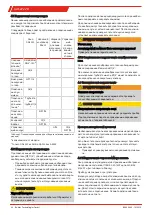
在安装本装置之前,请检查给出的技术数据与应用程序参
数是否相符。

您也应检查供货范围内的所有部件是否完备。

您可从铭牌上辨识其规格。在铭牌上,除了订单号/ID号,您还
可找到产品编号和型号名称。

请在连接时留意过滤器的参数,在订购备件时留意正确的版
本。

1.2 铭牌

例如:

制造商及其地址

型号名称

订单号,产品编号

材料

电力供应

GAS 222.20

100107323 462220009902000112213 001

230V 50/60Hz 440W

material: 1.4571/1.4408/PTFE

Read manual!

1.3 供货范围

1个气体取样探头

1 x 法兰垫圈和螺纹紧固件

产品文档

连接与安装附件(仅作为选件)

2 安全提示

仅能由熟悉安全要求和风险的专业人员安装该设备。

请务必遵守安装地相关的安全法规和普遍适用的技术规则。请
预防故障发生,避免人身伤害和财产损失。

设备操作员必须确保:

安全提示和操作说明书可供翻阅并予以遵守,

遵守国家有关事故预防条例,

不得超过允许的数据并遵循适用条件,

使用保护装置和进行规定的维护工作,

弃置处理时,遵守法例条文,

遵守有效的国家安装规定。

危险

电压

有触电的危险

a)

在进行所有作业时,断开设备电源。

b)

确保设备不会意外地再次开启。

c)

仅能由训练有素的人员打开设备。

d)

注意电源电压是否正确。

危险

有毒和腐蚀性气体

样气有可能是有害的

a)

请在排放样气时选择不会对人身健康带来危害的区域。

b)

维护设备前,请关断气路连接并保证不会无意间被重新开
启。

c)

在维护设备时注意自我保护,防止有毒、有腐蚀性气体对
自身造成伤害。必要时,使用手套,防毒面具和防护面
罩。

危险

潜在爆炸性环境

应用于易爆区域中有爆炸危险

该设备不适用于易爆区域中。

禁止将可燃或爆炸性气体混合物输送通过设备。

3 运输和储存

只应在原包装或合适的替代包装中运输产品。

在不使用时,应对设备加以保护,防止其受潮受热。必须将其
储存于-20°C至50°C (-4 °F bis 122 °F) 下的封顶的、
干燥且无尘的室内。

4 安装和连接

4.1 安装地点要求

气体取样探头被设计用于法兰安装。

安装的地点和位置由应用程序的相关条件确定。

如果可能的话,安装支架应向管道中心轻微倾斜。

安装地应不受天气影响。

请为安装以及后续的维护工作,确保空间足够且安全地能
接触到。请尤其注意探管的设计长度!

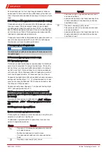
如果探头以零件的形式送达安装现场,则必须首先对它进行组
装。

4.2 采样管(可选)的组装

必须拧入必要时带有合适的延长部分的采样管。之后,使用附
带的垫圈和螺母将探头固定至对接法兰盘上。

25

Bühler Technologies GmbH

BX460040 

 10/2019

Summary of Contents for GAS 222.20

Page 1: ...040 Version 10 2019 Ref 998BX460040 Analysentechnik Kurzanleitung Sonden deutsch 2 Brief Instructions Probes english 8 Notice de montage Sondes fran ais 13 Gu a r pida Sondas espa ol 19 chinese simpli...

Page 2: ...n Sie beim Anschluss die Kennwerte des Ger tes und bei Ersatzteilbestellungen die richtigen Ausf hrungen 1 2 Typenschild Beispiel GAS 222 20 100107323 462220009902000112213 001 230V 50 60Hz 440W mater...

Page 3: ...Voraussetzungen bestimmt Falls m glich sollte der Einbaustutzen eine leichte Nei gung zur Kanalmitte haben Der Einbauort sollte wettergesch tzt sein Ebenfalls muss auf ausreichenden und sicheren Zuga...

Page 4: ...n gesundheitssch dlich sein Pr fen Sie die Leitungen auf Dichtheit 4 5 2 Anschluss der Kalibriergasanschlussleitung optional Zum Anschluss der Kalibriergasleitung wird eine Rohrver schraubung 6 mm bzw...

Page 5: ...bereich der Sonde und die Temperatureinheit C F werden mittels der drei Bedientas ten der Steuerung eingestellt Dies ist im Kapitel Betrieb und Bedienung beschrieben Die Werkseinstellungen sind Einhei...

Page 6: ...ahlweise Celsius oder Fahrenheit Anzeige Temperatur Wahlmen Wahlmen Exit Wahlmen Exit Anzeige Top Settings R cksp lintervall Alarm Wahlmen Sondentemperatur R cksp lzeit ____ Einstellbereich Setzen der...

Page 7: ...der Ori ginalbetriebsanleitung auf der beigef gten CD oder im Inter net unter www buehler technologies com 7 Service und Reparatur Eine ausf hrliche Beschreibung des Ger tes mit Hinweisen zur Fehlers...

Page 8: ...1 x Sample gas probe 1 x Flange gasket and screws Product documentation Connection and mounting accessories only optional 2 Safety instructions The equipment must be installed by a professional famil...

Page 9: ...ectly When seated correctly it locks onto the filter housing 4 4 Insulation On heated probes completely insulate any exposed flange areas and if applicable the connection piece to absolutely prevent t...

Page 10: ...ple gas dew point at the sample point The unit cannot be retrofit with a heated extension The connection cable for the heated extension mains connec tion 115 or 230 V AC must be connected per the encl...

Page 11: ...rature Selection menu Selection menu Exit Selection menu Exit Display Top Settings Blowback interval Alarm Selection menu Probe temperature Blowback time ____ Setting range Setting the alarm hysteresi...

Page 12: ...r s manual on the included CD or online at www buehler technologies com for maintenance informa tion 7 Service and Repair Please refer to the original operator s manual on the included CD or online at...

Page 13: ...a d signation de type Veuillez respecter les valeurs caract ristiques de l appareil lors du branchement et veillez commander les bonnes pi ces de rechange 1 2 Plaque signal tique Exemple Fabricant ave...

Page 14: ...e montage sont d termin s en fonc tion des conditions d application pertinentes Le support de montage doit avoir si possible une l g re inclinaison vers le milieu du conduit Le lieu d installation doi...

Page 15: ...yst me d analyse Apr s avoir branch toutes les conduites et contr l l tanch it l isolation doit tre remise en place et fix e avec pr cautions AVERTISSEMENT Fuite de gaz Le gaz de mesure peut tre dange...

Page 16: ...affichage est permanent La temp rature de consigne la zone de travail de la sonde et l unit de temp rature C F sont r gl es au moyen de trois touches de maniement de la commande Ceci est d crit au cha...

Page 17: ...Temp rature Menu de s lection Menu de s lection Exit Menu de s lection Exit Affichage Top Settings Intervalle de r trolavage Alarme Menu de s lection Temp rature de sonde Dur e de r trolavage ____ Pla...

Page 18: ...ns le mode d emploi original pr sent sur le CD fourni ou sur Internet en allant sur www buehler technolo gies com 7 Service et r paration Vous trouverez une description d taill e de l appareil ainsi q...

Page 19: ...lo Tenga en cuenta los valores caracter sticos del aparato para la conexi n y los modelos correctos para encargar repuestos 1 2 Placa de caracter sticas Ejemplo Fabricante y direcci n Denominaci n N d...

Page 20: ...plicaci n Si es posible el tubo de montaje debe presentar una lige ra inclinaci n hacia la mitad del conducto El lugar de instalaci n no debe quedar a la intemperie Adem s debe asegurarse de que el ac...

Page 21: ...colocar y a fijar el aislante con gran cuidado ADVERTENCIA Salida de gas El gas de medici n puede resultar nocivo para la salud Compruebe que los conductos no presenten fugas 4 5 2 Conexi n del conduc...

Page 22: ...peratura de ajuste la zona de trabajo de la sonda y la unidad de temperatura C F se establecen mediante los tres botones del sistema de control Esto aparece detallado en el cap tulo Uso y funcionamien...

Page 23: ...ra Men de selecci n Men de selecci n Salir Men de selecci n Salir del submen Pantalla Top settings Intervalo de retrolavado Alarma Men de selecci n Temperatura de sondas Tiempo de retrolavado ____ Opc...

Page 24: ...se pueden encontrar en el CD que se incluye y en Internet www buehler technologies com 7 Servicio y reparaci n Para obtener una descripci n m s detallada del dispositivo y recomendaciones recomendaci...

Page 25: ...gen Deutschland 49 0 2102 4989 0 49 0 21 02 49 89 20 1 1 ID 1 2 GAS 222 20 100107323 462220009902000112213 001 230V 50 60Hz 440W material 1 4571 1 4408 PTFE Read manual 1 3 1 x 2 a b c d a b c 3 20 C...

Page 26: ...8 1 6 mm 1 4 2 NPT 1 4 G1 2 NPT 1 4 G1 8 G1 4 NPT 1 4 1 1 2 GAS 222 xx ANSI GAS 222 xx AMEX 4 5 1 NPT 1 4 4 5 2 6 mm 1 4 6mm 1 4 4 6 1 kV 1 5 kV 4 6 1 115 V AC 50 60Hz 230 V AC 50 60 Hz 4 6 2 Pt100 1...

Page 27: ...GAS 222 20 5 1 2 Prob AdOn 5 2 3 27 B hler Technologies GmbH BX460040 10 2019...

Page 28: ...ALAr E ___ C F C 5s 50 C 200 C 122 F 392 F ____ 5 C 30 C 50 C 200 C 122 F 392 F 5 C 30 C 5s 99s Blow back controller AdOn bbc tEMP ALAr E E ____ ___ __ __ __ 0 5 min 99h59min 5 59 s ctrl tInt t_bb 28...

Page 29: ...GAS 222 20 6 CD www buehler technologies com 7 CD www buehler technologies com 29 B hler Technologies GmbH BX460040 10 2019...

Page 30: ...H Harkortstra e 29 40880 Ratingen Deutschland 49 0 21 02 49 89 0 49 0 21 02 49 89 20 1 1 o 1 2 GAS 222 20 100107323 462220009902000112213 001 230V 50 60Hz 440W material 1 4571 1 4408 PTFE Read manual...

Page 31: ...GAS 222 20 a b c d 3 20 C 50 C 4 F 122 F 4 4 1 4 2 4 3 90 4 4 31 B hler Technologies GmbH BX460040 10 2019...

Page 32: ...PN6 DN3 150 2 G3 4 NPT 1 4 G3 8 1 6 1 4 2 NPT 1 4 G1 2 NPT 1 4 G1 8 G1 4 NPT 1 4 1 1 2 GAS 222 xx ANSI GAS 222 xx AMEX 4 5 1 NPT 1 4 4 5 2 6 1 4 6 1 4 4 6 1 1 5 4 6 1 115 AC 50 60 230 AC 50 60 32 B h...

Page 33: ...GAS 222 20 4 6 2 Pt100 115 230 AC 5 5 1 5 1 1 C F C 180 C 10 C 5 1 2 Prob AdOn 5 2 3 33 B hler Technologies GmbH BX460040 10 2019...

Page 34: ...F 392 F Exit Exit Top Settings ____ 5 C 30 C 50 C 200 C 122 F 392 F 5 C 30 C 5 99 Add on Blow back controller AdOn bbc tEMP ALAr Exit E Exit E ____ ___ __ __ __ 0 5 99 59 5 59 ctrl tInt t_bb Control m...

Page 35: ...GAS 222 20 6 www buehler technologies com 7 www buehler technologies com 35 B hler Technologies GmbH BX460040 10 2019...

Page 36: ...ed extension Pt100 heated extension Pt100 probe Power supply extension heated extension Power supply extension Blowback status Blowback solenoid valve Status Automatic Manual Sample gas solenoid valve...

Reviews: