2
Installation
20
Installation and maintenance instructions Logano GE315 • Issue 02/2006
We reserve the right to make any changes due to technical modifications.
z
Slowly fill the boiler with water through the drain cock.
At the same time vent the system at the boiler flow
connection.
z
If a hub connection is leaking, first drain the water
through the drain cock.
z
Remove the return header.
z
Remove the nuts from the four tie bars and then the
bars themselves.
z
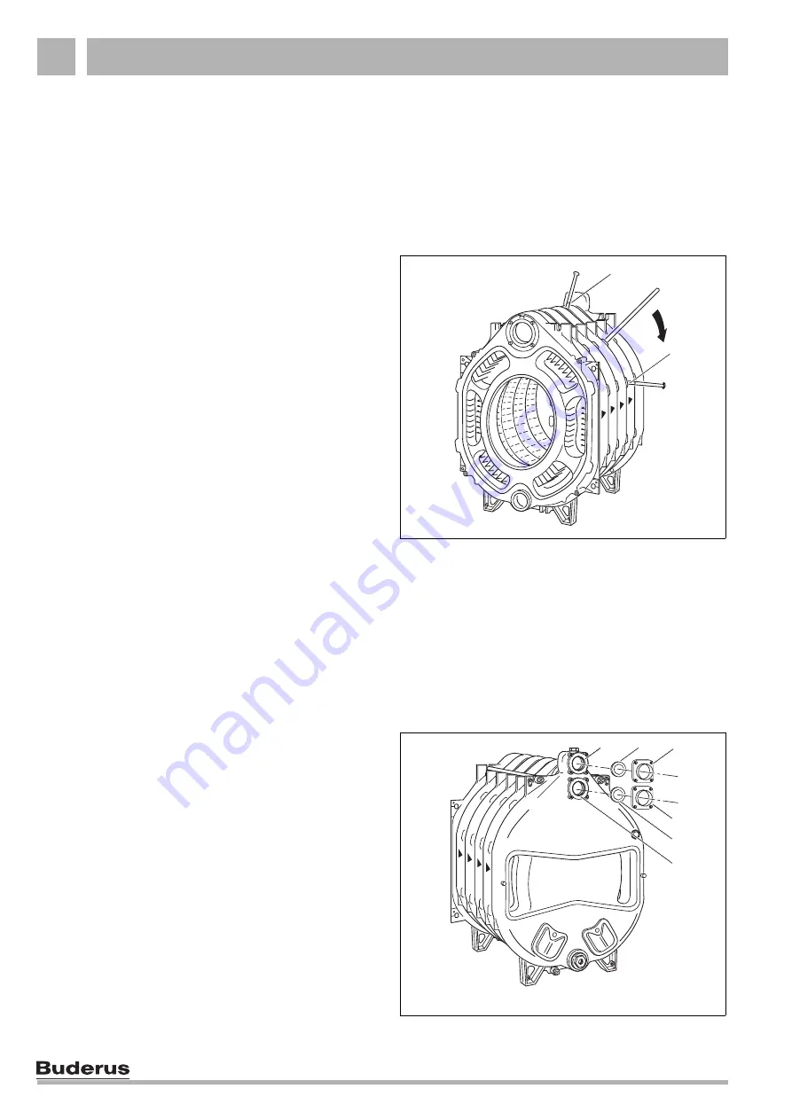
Separate the boiler sections by driving (hammering)
flat wedges or chisel at the points provided (Fig. 22,
Item 1 & 2
) at the top and bottom between the
relevant sections.
You must use new nipples and gaskets for the re-
assembly. Draw the boiler sections together and re-test
for leaks.
2.5.2
Test pressure
The test pressure during the leak test depends on the
design pressure for each individual heating system and
should be 1.5 times nominal pressure (normally 7.8 bar
for 30 minutes).
Use a pressure gauge class 1.0 for measuring the
pressure.
z
The weld neck flange is fitted to the upper boiler hub
(Fig. 23,
Item 6
– return connection) when the return
is installed later.
The illustration shows the weld neck flange and the
flat gasket (Fig. 23,
Item 4 & 5
).
z
The flow connection flange (Fig. 23,
Item 3
) and the
flat gasket (Fig. 23,
Item 2
) are required for the flow
connections which is fitted later (Fig. 23,
).
Fig. 22
Separating the boiler block
Fig. 23
Connection flange installation
1
2
3
5
6
1
2
4


