3
HR 200 & HR 300
En
6 720 804 927 (2015/07)
Installation
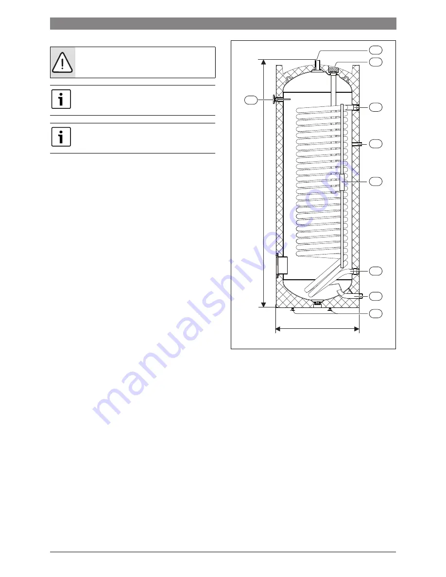
▶ Install the adjustment feet on the hot water cylinder (
[7]).
▶ Position the hot water cylinder on a level base.
▶ Install the sweep/cover on the hot water cylinder.
▶ Install the thermometer on the side of the hot water cylinder (
[8]).
▶ Install an automatic venting valve (E41.F111) on the inflow of the heat transfer
fluid (
[3]).
▶ Install a pipe for heat transfer fluid on the automatic venting valve (
[3]) and
install the three-way valve (E21.Q21) on the pipe.
▶ Connect the three-way valve to the indoor part of the heat pump.
▶ Install the flow sensor (E11.T1) on the other inlet to the three-way valve. The flow
sensor must be positioned at least one metre from the three-way valve. Refer to
the system diagram in the installer manual for the Heat Pump.
▶ Install pipes for the heat transfer fluid between the outlet for the transfer fluid
(
[5]) and the indoor part of the heat pump.
▶ Connect the power supply for the three-way valve (E21.Q21) to the circuit board
in the electric box of the indoor unit. Refer to the electric diagram in the installer
manual for the Heat Pump.
▶ Install the hot water sensor (E41.T3) in the dipstick pipe on the outside of the hot
water cylinder (
[4]). Position the sensor approximately 600 mm (HR200) or
approximately 800 mm (HR300) from the bottom of the cylinder.
▶ Connect the hot water sensor to the circuit board in the electric box of the indoor
unit. Refer to the electric diagram in the installer manual for the Heat Pump.
▶ Connect domestic hot water (
[1]) and domestic cold water (
[6]).
Hot water sensor T3
If a hot water cylinder is installed and T3 is connected to the system, T3 is
automatically acknowledged at start-up.
Hot water is prioritised and controlled by the sensor T3 in the hot water cylinder.
While water is being heated in the cylinder, the heating system from the heat pump
is temporarily disconnected thorugh the three-way valve. The heating operation
from the heat pump continues when the water in the cylinder has reached the set
temperature.
Fig. 2
How water cylinder (mm)
1
Hot water, out
2
Sacrificial anode
3
Heat transfer fluid, in
4
Positioning sensor
5
Heat transfer fluid, out
6
Cold water, in
7
Adjustable feet
8
Thermometer
9
DHW circulation G3/4"
WARNING:
Make sure that the floor can hold 108 + 200 kg (HR
200) or 140 + 300 kg (HR 300).
Keep the installer manual for the Heat Pump available as a
reference for the relevant system solutions and wiring diagrams.
An automatic venting valve must be installed when a hot water
cylinder is connected to the system.
Ø 600
HR 200 = 1340, HR 300 = 1797
4
8
1
2
3
5
6
7
6720804927-01.1TL
9


