background image

Actions

7

We reserve the right to make technical modifications

Buderus Ltd. • http://www.buderus-domestic.co.uk

68

Servicing manual Gas condensing boiler Buderus 500-24/S, 500-24/C and 500-28/C • Issued 02/2006

box 243

z

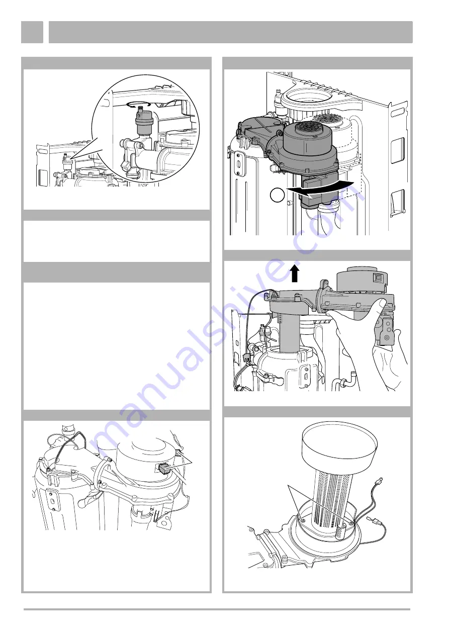
Twist the automatic air vent in the direction of the arrow to 
remove.

box 244

z

Fit the new automatic air vent by following the above 
procedure in reverse order.

z

Fill the heating system, vent it of air and place the boiler 
into operation, see box 52 to 58.

box 245 Replace the burner

H

DANGER OF FATAL ACCIDENT


due to electric shock

A

DANGER OF FATAL ACCIDENT!


All work on gas supply pipes and gas-fitting 
components must be carried out by a company 
registered and authorised for this purpose.

z

Take the boiler out of operation and close the gas tap, 


see box 43, 4446 or 47.

z

Remove the power supply plug of the glow ignitor, 


see box 131.

z

Remove the plug of the ionisation electrode, see box 144.

z

Remove the power supply plug of the gas valve, union nut 
and air silencer tube, see box 77.

box 246

z

Pull out both fan plugs (item 1).

1

box 247

z

Turn the gas/air unit clockwise by about 10°.

box 248

z

Remove the gas/air unit along with the burner.

box 249

z

Loosen both screws (item  1).

z

Remove the burner.

1

1

Summary of Contents for 500 - 24/C

Page 1: ...7214 8900 02 2006 GB EN For the installer Please read thoroughly before attempting fault diagnosis Servicing manual Gas wall hung Boiler condensing Buderus 500 24 S Buderus 500 24 C Buderus 500 28 C...

Page 2: ...ate standards and directives Conformity has been substantiated by the proper documents which together with the declaration of conformity are filed with the manufacturer Subject to technical modificati...

Page 3: ...the service instructions Installation maintenance and repair must be carried out by competent service engineers e g CORGI registered Only use the boiler in conjunction with the accessories and spare p...

Page 4: ...entire system to see if it is in full working order Defects and faults must be eliminated immediately I NOTE When instructions aren t followed warranty expires I NOTE Condensing boilers work more effi...

Page 5: ...st be in accordance with BS 5546 and BS 6700 z The boilers are suitable for connection to most types of washing machine and dishwasher appliances z When connecting to suitable showers ensure that a Th...

Page 6: ...107 107 107 Boiler efficiency 40 30 C upper value partial load 96 3 96 3 96 3 Boiler efficiency 75 60 C lower value upper value full load 95 7 86 2 95 7 86 2 95 7 86 2 Boiler efficiency 75 60 C lower...

Page 7: ...d W 110 Dimensions and weight of boiler height width depth mm 780 460 330 780 460 330 780 460 330 Weight without casing Weight with casing kg kg 30 33 31 34 31 34 Gas Category of gas as per EN 437 for...

Page 8: ...fications Buderus Ltd http www buderus domestic co uk 8 Servicing manual Gas condensing boiler Buderus 500 24 S 500 24 C and 500 28 C Issued 02 2006 box 6 Overview Buderus 500 1 2 3 4 5 7 11 12 13 14...

Page 9: ...trol panel Item 29 RTH converter junction box box 8 General points A WARNING DANGER OF FATAL ACCIDENT FROM EXPLOSIVE FUMES If you smell gas z There is a danger of explosion z No naked lights No smokin...

Page 10: ...ee box 228 o box 43 step 39 Check to ensure that the Buderus 24V AC external three way valve is actuated correctly see box 213 and box 229 step 40 Does the Buderus 24V AC external three way valve actu...

Page 11: ...eneral points The central boiler can be run from the DBA control panel item 1 1 box 11 item 1 Mains switch 0 1 item 2 Reset button item 3 Service button item 4 Display item 5 Menu button item 6 Adjust...

Page 12: ...es in service mode The maximum CH flow temperature as configured in the Settings menu applies in this case step 5 Briefly press the C button step 6 Partial load service mode lo is activated Check the...

Page 13: ...K L Configured heating mode As soon as pr is displayed you can verify the current heating mode or adjust it as required See also box 18 step14 Adjust configured heating mode Yes step 15 No step 16 ste...

Page 14: ...20 The boiler is ready for operation No current heat requirement step12 Start of pump over run time via the heating system The pump over run time via the heating system factory adjusted to 5 minutes v...

Page 15: ...oes the ionisation current exceed 1 4 A microamperes within 5 seconds Yes step 32 No step 72 step32 C h The boiler is in hot water mode If there has been a power cut The startup load on the boiler is...

Page 16: ...rature 6 C lower than the target setting Yes step 47 No step 53 step57 The symbol K goes out step58 C 0h The gas valve is closed and the burner is shut down step59 The symbol G goes out step60 Start o...

Page 17: ...the locking is by pushing the reset B button box 16 Display icons Display indication Key to display indication F Service mode G Ionisation signal flame monitoring H Hot water mode ECO setting or hot...

Page 18: ...equirement arises C 0e Ready for operation The boiler is in ready mode There is a current heat requirement but too much energy has been supplied C 0h Standby for operation The boiler is in ready mode...

Page 19: ...ent ionisation current No 1 box 36 6a Fault After four startup attempts the system has detected an insufficient ionisation current Yes 2 No heating operation and no hot water box 36 6c Fault The syste...

Page 20: ...ater box 41 e1 to e4 ea ec Fault The DBA control panel is defective Yes 2 No heating operation and no hot water box 41 C re Fault Reset is carried out This code appears after the reset button B is pre...

Page 21: ...of box 42 step 13 Use a multimeter to check the fuse on the inside of the DBA control panel see box 62 to 65 step 14 Is the fuse working correctly Yes box 41 No step 15 step 15 Replace fuse see box 62...

Page 22: ...does not lie with the boiler but with the mains water supply Check to see if the MCW inlet and DHW outlet have been incorrectly connected to the external storage type water heater step 6 Are the pipe...

Page 23: ...internal 3 way valve fitted Yes step 34 No step 32 step 32 Check the movement of the servomotor of the Buderus 24V AC external 3 way valve see box 211 step 33 Does the servomotor of the Buderus 24V AC...

Page 24: ...the cable loom or the affected part thereof box 42 step 63 Check to ensure that the Buderus 24V AC external 3 way valve has actuated correctly see box 212 and box 228 parts 1 and 2 step 64 Does the B...

Page 25: ...14 and box 61 step 12 Is the CH flow temperature adjusted to a high enough setting Yes step 13 No step 15 step 13 Are enough thermostatic valves open on the radiators convectors etc Yes step 16 No ste...

Page 26: ...e the wiring of the Buderus 24V AC external 3 way valve box 42 step 45 Check the drive mechanism of the Buderus 24V AC external 3 way valve see box 221 step 46 Is the drive mechanism of the Buderus 24...

Page 27: ...tep 7 No step 6 step 6 Replace the thermostat cable box 42 step 7 Check to ensure that enough thermostatic valves are open on the radiators convectors etc step 8 Are enough thermostatic valves open on...

Page 28: ...ult code The flow NTC sensor and safety sensor have detected a CH flow temperature of over 105 C Locking boiler fault code Short circuit between flow NTC sensor or safety sensor Locking boiler fault c...

Page 29: ...gas STL in full working order Yes box 41 No step 12 step 12 Replace the cable loom or the affected part thereof box 42 box 29 The tacho signal from the fan has failed during the operating phase Block...

Page 30: ...4 No step 3 step 3 Reconnect the plug and socket connection see box 78 item 2 box 42 step 4 Check tacho cable of fan see box 73 step 5 Is the tacho cable in full working order Yes step 7 No step 6 st...

Page 31: ...f the cable loom see box 116 box 42 box 34 The contacts of the flow NTC sensor and safety sensor are shorted to each other or there is a short circuit to earth ground or the flow or safety sensor has...

Page 32: ...er fault code step 1 Is the heating system propane gas fired Yes step 2 No step 3 step 2 Ensure that no nitrogen remains in the gas tank or gas flow pipes You should also consult your gas utility comp...

Page 33: ...and socket connection on the gas valve see box 161 step 29 Is the plug and socket connection in full working order Yes step 31 No step 30 step 30 Reconnect the plug and socket connection at the gas va...

Page 34: ...p 52 Check the plug and socket connection between the ionisation electrode and cable loom see box 144 step 53 Is the plug and socket connection in full working order Yes step 55 No step 54 step 54 Cor...

Page 35: ...at the operating switch step 14 The following components should be checked for soiling damage and or correct installation syphon see box 256 flue gas pipework step 15 Check the pressure control valve...

Page 36: ...ctly connected and free of damage Yes step 7 No step 6 step 6 Replace the cable loom or the affected part thereof box 42 step 7 Measure the resistance of the gas valve coils see box 171 step 8 Is the...

Page 37: ...us 500 24 S 500 24 C and 500 28 C Issued 02 2006 37 box 42 step 1 Fit the casing to the boiler step 2 Turn the mains switch on the DBA control panel of the boiler to position 0 OFF see box 43 step 3 T...

Page 38: ...em 1 box 44 z Turn the mains switch to OFF box 45 Key to terms see box 4 1 CH flow 2 DHW outlet combination boilers only 3 Gas connection 4 MCW inlet combination boilers only 5 CH return z Close the s...

Page 39: ...ing and use the radiator key to turn the casing lock to closed 6 1 2 3 4 5 box 52 Filling the system and venting it of air z Turn the operating switch on the boiler to position 0 OFF see box 43 z Remo...

Page 40: ...ting of the pump will help ensure that it runs for its specified service life The sliding bearing which is located behind the vent screw is lubricated with heating system water z Once the heating syst...

Page 41: ...l panel forwards item 2 1 1 2 box 64 z Remove the rear section of the DBA control panel see box 70 z Remove the fuse from the fuse holder z Check the fuse with a multimeter If the fuse possesses infin...

Page 42: ...ply cable 230 V AC H DANGER OF FATAL ACCIDENT due to electric shock A CAUTION To prevent damage do not insert the measuring electrodes of the multimeter too far into the holes of the plug and socket c...

Page 43: ...the tacho cable of the fan for internal short circuits The level of electrical resistance measured between two wires chosen at random must be infinitely high box 75 z Connect the tacho cable plug z Re...

Page 44: ...box 84 z Fit the fan to the boiler Remember to fit the new flat rubber sealing ring supplied when doing so z Fit the air silencer tube to the fan z Fit the gas supply pipe to the gas valve Ensure whe...

Page 45: ...see box 77 z Remove the Venturi see box 81 item 1 1 2 3 4 5 6 A 7 box 87 z Check the article number of the Venturi against those listed in the table in box 5 z Check to ensure that the correct Ventur...

Page 46: ...f the power supply plug of the pump during locking fault code 2l box 94 z Insert the power supply plug of the pump z Fit casing see box 51 box 95 Check the pump power supply cable H DANGER OF FATAL AC...

Page 47: ...see box 43 44 47 45 49 or 50 z Remove the power supply plug of the pump see box 92 box 102 z Loosen the union nuts item 1 at the top and side of the pump z Remove the pump box 103 A CAUTION Fit new fl...

Page 48: ...e resistance of the safety sensor box 107 z Pull out the plug of the flow NTC sensor box 108 z Set multimeter to measure resistance z Measure the resistance of the flow NTC sensor box 109 z Measure th...

Page 49: ...lug and socket connection z Take the boiler out of service and tip the DBA control panel forwards see box 43 44 47 or 63 z Loosen the six screws and remove the rear section see box 70 z Pull out the p...

Page 50: ...safety sensor z Take the boiler out of operation drain the heating system and pull out the plug of the corresponding sensor see box 43 44 47 45 47 49 or 50 1 2 3 4 5 6 7 Room Controller Hot water tan...

Page 51: ...NGER OF FATAL ACCIDENT due to electric shock z Take the boiler out of service and tip the DBA control panel forwards see box 43 44 47 or 63 z Loosen the six screws and remove the rear section see box...

Page 52: ...he boiler into operation see box 54 55 or 51 1 box 134 Check the glow ignitor resistance H DANGER OF FATAL ACCIDENT due to electric shock z Take the boiler out of operation see box 43 44 or 47 z Remov...

Page 53: ...the boiler into operation see box 51 54 or 55 box 140 Replace the glow ignitor H DANGER OF FATAL ACCIDENT due to electric shock z Take the boiler out of operation see box 43 44 or 47 z Remove the plug...

Page 54: ...box 144 box 149 z Set multimeter to measure resistance z Take a reading at the electrode to check whether there is a possible short circuit between the ionisation electrode and earth ground The electr...

Page 55: ...isation electrode item 1 z Remove the mounting plate item 2 z Detach the ionisation electrode item 3 box 157 z Set multimeter to measure resistance z Take a reading at the ionisation electrode to chec...

Page 56: ...4V DC must be detectable at both the centre and upper contacts item 1 and 2 box 166 z Put the boiler into operation see box 51 54 or 55 box 167 Check gas valve electrical resistance of power supply ca...

Page 57: ...gas valve to the fan z Fit the fan to the boiler insert the air silencer tube into the fan fit the gas supply pipe to the gas valve and insert the plugs into the fan and gas valve z Fit the air silen...

Page 58: ...low regulator in direction To reduce the DHW flow rate turn the flow regulator in direction z Adjust the flow rate of hot water at one of taps where the user is likely to require hot water at an ideal...

Page 59: ...plug in contacts 1 and 2 z Close the hot water tap z Check to see if during operating code C 0h 24 V AC is detected at plug in contacts 1 and 2 1 2 0 3 0 box 189 z Insert the power supply plug of the...

Page 60: ...omotor of the 3 way valve see box 182 box 196 z Check to ensure that the drive mechanism of the 3 way valve is running smoothly This is done by gradually pushing the spring fully home by hand and allo...

Page 61: ...boiler into operation see box 52 to 58 box 203 Replace the internal 3 way valve z Take the boiler out of operation and drain the heating system see box 48 to 51 box 204 z Disconnect the cable from the...

Page 62: ...at water will squirt out when the internal 3 way valve is removed Have a bucket and a supply of dry cloths to hand 1 2 2 1 2 3 3 H3 3 2 1 box 209 z Replace the housing of the 3 way valve box 210 z Ref...

Page 63: ...detected at plug in contacts 2 and 3 Plug in contacts of Buderus 24V AC external 3 way valve Purpose Plug incontacts on DBA control panel 2 24V AC 5 3 0V AC 6 6 _ __ 7 6 3 2 box 216 z Insert the power...

Page 64: ...e drive mechanism z Take the boiler out of operation see box 43 or 44 z Remove the servomotor of the Buderus 24V AC external 3 way valve see box 218 box 222 z Check to ensure that the drive mechanism...

Page 65: ...5 and item 6 box 229 z Fit the DBA control panel and place the boiler into operation see box 51 54 or 55 Plug incontacts on DBA control panel Purpose Plug in contacts of Buderus 24V AC external 3 way...

Page 66: ...see box 59 z Use a detection product to check the gas connection pressure measurement nipple for leaks Use an authorised foam type leak detection product for this purpose z Fit the casing and place t...

Page 67: ...55 box 239 Vent the gas flow pipe A DANGER OF FATAL ACCIDENT All work on gas supply pipes and gas fitting components must be carried out by a company registered and authorised for this purpose z Take...

Page 68: ...OF FATAL ACCIDENT due to electric shock A DANGER OF FATAL ACCIDENT All work on gas supply pipes and gas fitting components must be carried out by a company registered and authorised for this purpose z...

Page 69: ...k check Check the tightness of all components that were loosened in the course of removal of the burner Use an authorised foam type leak detection product for this purpose z Remedy the cause of the ga...

Page 70: ...w ignitor see box 131 z Remove the plug of the ionisation electrode see box 144 z Remove the power supply plug of the gas valve union nut and air silencer tube see box 77 z Pull out both fan plugs see...

Page 71: ...he heat exchanger with compressed air a high pressure hose or with water and a soft brush A CAUTION When cleaning the heat exchanger never use a steel brush A CAUTION When using compressed air Use eye...

Page 72: ...m vent it of air open the gas tap and place the boiler into operation see box 59 or 52 to 58 box 269 Replace plate heat exchanger z Take the boiler out of operation see box 43 44 or 47 z Close the col...

Page 73: ...out of operation and drain the heating system see box 48 to 50 box 276 z Remove the stop spring item 2 of the pressure relief valve z Remove the pressure relief valve item 1 in the direction of the ar...

Page 74: ...KIM see box 284 The coloured stripe on the new KIM should match that of the old KIM Otherwise refit the old KIM to the new DBA control panel z Fit the casing and place the boiler into operation see b...

Page 75: ...28 C Issued 02 2006 75 box 286 Check the junction box 0 Volt room temperature connection z Remove the casing lock and lower the DBA see box 285 z Remove the cover from the RTH converter junction box s...

Page 76: ...15 16 13 12 11 10 17 9 8 10 L N L N L N 2 3 1 2 3 1 2 4 1 4 5 1 5 2 3 1 2 3 1 safety sensor flow sensor Turbine hot water sensor gas valve ionisation electrode flue gas thermostat fan pump glow ignit...

Page 77: ...ay valve activation box 185 Check the internal 3 way valve drive mechanism box 195 Check the internal 3 way valve movement of the servomotor box 181 Check the internal 3 way valve power supply cable b...

Page 78: ...Notes We reserve the right to make technical modifications Buderus Ltd http www buderus domestic co uk 78 Servicing manual Gas condensing boiler Buderus 500 24 S 500 24 C and 500 28 C Issued 02 2006...

Page 79: ...Notes We reserve the right to make technical modifications Buderus Ltd http www buderus domestic co uk Servicing manual Gas condensing boiler Buderus 500 24 S 500 24 C and 500 28 C Issued 02 2006 79...

Page 80: ...ww buderus domestic co uk Customer Services Technical Product Support Sales Returns Spares Tel 0870 421 5933 Tel 0870 421 5944 Tel 01905 752 640 Tel 01905 752 531 Tel 01905 752 576 Fax 01905 456 445 4...

Reviews: