background image

深圳市比特视讯有限公司

14

页 共

25

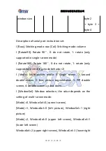
Remote control operation instructions

The adjustment of the following two groups of parameters

needs to press the [Ent] confirmation key to take effect, and

the [Esc] cancel key can be pressed when the parameter

setting needs to be cancelled.

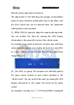
(1) [ROW, COL] is a group to adjust the output splicing mode.

You can confirm the value by viewing the OSD display

information in the upper left corner of the whole screen.

For example: if you need to adjust to 2x3 (two rows and three

columns) splicing mode, you need to set [row] to 2, and [COL]

to 3. Press [Ent] to confirm, and then the splicing mode will be

changed to 2x3.

(2) [Src, Win] is a group. The purpose is to arbitrarily specify

the input source channel of each screen (window) in the

"whole screen". You can confirm the value by viewing the OSD

display information in the "upper left corner of the whole

screen".

For example: Currently, it is [

] PIP mode,HDMI is displayed

Summary of Contents for BIT-VWC-406R

Page 1: ...ions 4 3 Operation instructions 6 3 1 Product panel description 6 3 2 Remote control function description 10 3 3 Product connection diagram 19 3 4 Definition of rows and columns 21 3 5 Supported resolution 22 4 Common problems 24 5 Appendix 25 5 1 Appendix 1 Arrangement of output interface 25 深圳市比特视讯有限公司 BIT VWC 406R ...

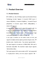
Page 2: ... out can be combined in any number of splicing modes horizontal screen vertical screen 2X2 and support large scale parallel operation in the form of loop out It can open 4 windows on the whole screen at most and supports multiple window opening modes Single screen PIP double screen double screen Four picture segmentation The input supports a maximum of 3840x2160 60Hz and is backward compatible The...

Page 3: ...ctive heat dissipation is used internally without any external heat dissipation measures and the reliability is extremely high Support Computers Android boxs game consoles and other devices as input source Using 40nm high end programmable FPGA chip full hardware real time processing architecture ultra fast processing speed without delay 1 2 Application scenarios It is mainly used in industrial app...

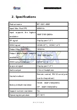
Page 4: ... HDMI 2 0 1 HDMI 1 4 3 Output Max Pixel FPS 165MHz Output single screen support resolution 1920 1080 60Hz HDMI output interface HDMI 1 3 6 Loop out signal Display port 1 2 1 Audio output 3 5mm Headphone Control method Remote control RS232 serial port can be looped out Factory default resolution HDMI 3840 2160 60Hz DP 3840 2160 60Hz Support custom resolution Yes Operating temperature 0 50 ...

Page 5: ...比特视讯有限公司 第 5 页 共 25 页 Power consumption 12W Power supply 12V 2A AC DC Weight 840g Size 270mm 122 5mm 20mm Annex One DP Cable One 12V 2A AC DC One remote control Power Supply 12V 2A AC DC Warranty One year ...

Page 6: ...d for the control system to issue instructions to control the device C Industrial seat used for RS232 control used to issue RS232 commands D Dip switch Board id indicates the ID of the current device in cascade mode V406 does not support this function only V409 supports it E IR is used for receiving remote control signals Need external IR receiver F G H I 4 HDMI input ports of which I port is 4K60...

Page 7: ... K Audio output interface used for audio output devices earphones etc L DP ring output interface when multiple devices are cascaded It acts as a DP input source for other devices or displays The LED light loop next to the interface indicates that there is a loop out signal output In single screen mode the loop out follows the selection of the input source channel to switch In non single screen mod...

Page 8: ...ed P Connect the light which means the video signal is connected normally Q R S T U V 6 HDMI output interfaces used to connect display devices such as monitors televisions or monitors There is an LED next to each HDMI interface The light is on indicating that there is a signal output from the HDMI interface Note 1 DIP switch when cascading it indicates the ID number of the current device which is ...

Page 9: ...inary ID number Binary Device 1 1000 Device 9 1001 Device 2 0100 Device 10 0101 Device 3 1100 Device 11 1101 Device 4 0010 Device 12 0011 Device 5 1010 Device 13 1011 Device 6 0110 Device 14 0111 Device 7 1110 Device 15 1111 Device 8 0001 ...

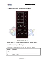
Page 10: ...e control function description Remote control panel Remote control panel description In the case of outputting a complete image explain the keys Full screen The output screen put together as a whole Remote button Features Ent Confirm key ...

Page 11: ...the source 1 for HDMI 2 for DP Cooperation Zoom to realize the function of move left right zoom in zoom out of small window in picture Cooperation Zoom to realize the function of move left right zoom in zoom out of small window in picture zoom Picture in picture Small window move left and right menu small window move up and down menu small window zoom in and out menu Four picture select the input ...

Page 12: ...he whole input image 90 only in the case of single image R180ᵒ First line output image rotated 180 only in case of 2 lines Clone Clone mode copy display 1x1 for each output port Note 1 win key meaning window the number of each screen window in the whole screen the corresponding screen position is as follows Single screen mode there is only one screen and the value is fixed as number 1 as shown bel...

Page 13: ... The left screen value is No 1 and the right screen value is No 2 as shown below Double picture Up down mode The upper screen value is No 1 and the lower screen value is No 2 as shown below Four screen mode The value of the upper left screen is No 1 the value of the lower left screen is No 2 the value of the upper right screen is No 3 and the value of the lower right screen is No 4 as shown in the...

Page 14: ...g the OSD display information in the upper left corner of the whole screen For example if you need to adjust to 2x3 two rows and three columns splicing mode you need to set row to 2 and COL to 3 Press Ent to confirm and then the splicing mode will be changed to 2x3 2 Src Win is a group The purpose is to arbitrarily specify the input source channel of each screen window in the whole screen You can ...

Page 15: ...key The large screen window can be switched to DP signal source Set Win to 2 window No 1 means small screen window set Src to 1 2 means HDMI input After pressing the Ent confirmation key The small screen window can be switched to HDMI signal source RS232 control Serial port instruction parameter setting baud rate 9600 bps data bit 8 bits stop bit 1 bit no parity bit Function Byte 1 cmd_h ead Byte ...

Page 16: ...x00 byte 1 byte 2 byte 3 byte 4 Multi pictures mode 0x66 0x04 Mode 0x00 byte 1 byte 2 byte 3 byte 4 Multi pictures win dow specify input source 0x66 0x05 Window Sel Source Channel byte 1 byte 2 byte 3 byte 4 PIP Small window position 0x66 0x06 Position 0x00 byte 1 byte 2 byte 3 byte 4 PIP Small0x66 0x07 Size 0x00 byte 1 ...

Page 17: ...e only supported in stitching mode behavior 2 l Mode Multi picture mode 0 single screen 1 around double screen 2 four picture segmentation 3 PIP double screen 4 double screen up and down l WindowSel Window selection the value depends on the setting of multi screen mode Mode 0 WindowSel 0 current screen Mode 1 WindowSel 0 left picture WindowSel 1 right picture Mode 2 WindowSel 0 upper left screen W...

Page 18: ...DMI 2 2 is HDMI 3 3 is HDMI 4 4 is DP 5 l Position Choose the position of the small window in the picture in picture mode 0 center 1 upper left corner 2 upper right corner 3bottom left corner 4 Bottom right corner only supported in PIP double screen mode l Size Choose the size of the small window in the picture in picture mode 0 10 the larger the value the larger the window supported in PIP double...

Page 19: ...Product connection diagram 1 Instructions for single unit Take 2x3 as an example Front panel wiring diagram 2x3 mode front panel wiring diagram The board ID of the dial switch on the front panel of the current device needs to be set ...

Page 20: ...深圳市比特视讯有限公司 第 20 页 共 25 页 2x3 mode front panel dial switch dial method ...

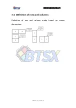
Page 21: ...深圳市比特视讯有限公司 第 21 页 共 25 页 3 4 Definition of rows and columns Definition of row and column mode based on screen dimensions ...

Page 22: ...r details please contact the company Form 1 BIT V406R Equal proportion mode supported by video card application Mode Full screen input resolution Full screen output resolution Single screen resolution 1x2 3840x1080 30Hz 3840x1080 60H Z 1920x1080 60HZ 1x3 3840x720 30HZ 5760x1080 60H Z 1920x1080 60HZ 1x4 3840x540 60HZ 7680x1080 60H Z 1920x1080 60HZ 1x5 3840x432 60HZ 9600x1080 30H Z 1920x1080 60HZ 1x...

Page 23: ...920x1080 60HZ 2x3 3840x1440 30HZ 5760x2160 60H Z 1920x1080 60HZ 3x1 1920x3240 30HZ 1920x3240 60H Z 1920x1080 60HZ 3x2 2816x2376 30HZ 3840x3240 60H Z 1920x1080 60HZ 4x1 1776x3996 30HZ 1920x4320 60H Z 1920x1080 60HZ 5x1 1408x3960 30HZ 1920x5400 60H Z 1920x1080 60HZ 6x1 1184x3996 30HZ 1920x6480 60H Z 1920x1080 60HZ ...

Page 24: ...mote control switch does not respond Answer Because it involves resolution switching it takes a certain time 1s If the display does not meet the expectations it can be restored by power off again 4 Image rotation image does not rotate is there the simplest way to remember the number of output screen Answer yes we have The number follows from top to bottom left to right it s just that your head loo...

Page 25: ...output interface When the image is not rotated the output interface is first up then down first left then right As shown in the following 2x3 mode When the image is rotated 90ᵒ The output interface is first up then down first left then right As shown in Figure 3x2 mode ...

Reviews: