background image


BTSR International S.p.A. 


Via S. Rita 


21057 OLGIATE OLONA (VA) 

 Tel. 

0331-323202 

 Fax 

0331-323282 

 Internet: 

www.btsr.com 

REV. 1.2 – 02/12 


DISTRIBUTORE 


Summary of Contents for SMART MATRIX WINDINGFEEDER

Page 1: ...SMART MATRIX WINDINGFEEDER Operating Manual ENGLISH Rev 1 2 July 2012 ...

Page 2: ... any time the contents of this Manual without notice For any technical or commercial problem please contact your local BTSR dealer or call directly BTSR customer service center We will be glad to meet your needs Thank you for your trust and good job The product described herein is compliant with the requirements of Machine Directive 2006 42 CE and EMC Directive 2004 108 EC All BTSR products are co...

Page 3: ...Introduction i ...

Page 4: ......

Page 5: ...y program all the operating parameters of WINDINGFEEDER devices in addition it provides a real time monitoring of device behavior and production efficiency Manual Objectives This manual has been written to provide the users of SMART MATRIX WINDINGFEEDER system with the essential information required to Correctly install and connect the various system components SMART MATRIX terminal and WINDINGFEE...

Page 6: ...rmation In the program function descriptions this symbol indicates the function e g IDENTIFY within the menu item e g SETUP Reference Documentation For detailed information about the operation interface and local programming mode of WINDINGFEEDER devices please refer to the WINDINGFEEDER Manual Edition March 2011 SETUP IDENTIFY ...

Page 7: ...Numbering 12 SMART MATRIX WINDINGFEEDER Code 14 I O Configuration on SMART MATRIX WINDINGFEEDER 15 Efficiency Calculation Mode 16 Keycode Setting 17 Communication Test 19 Device Offset 20 Language Selection 21 SMART MATRIX LCD Display Adjustment 23 Information about SMART MATRIX WINDINGFEEDER 24 Style Programming 25 Style Loading 30 Graphics Display 32 Alarm Counter Display 34 3 System Information...

Page 8: ...Indice SMART MATRIX WINDINGFEEDER iv ...

Page 9: ...Connections and Electrical Interface 1 ...

Page 10: ......

Page 11: ...INDINGFEEDER devices and PC The PC is mainly used for firmware update operations on SMART MATRIX WINDINGFEEDER Terminal For a correct connection of WINDINGFEEDER device supply and interface cables please refer to Section 2 of WINDINGFEEDER Operating Manual On all electrical systems you are kindly recommended to connect the ground cable GND to the support on which the devices are installed ...

Page 12: ...necessary press the small P button Technical characteristics of SMART MATRIX WINDINGFEEDER terminal Power supply voltage 24 VDC 10 Current absorption 100 mA Max Protection fuse SMART MATRIX 1 5 A Protection fuse Sensor power supply 1 5 A 0 24 VDC VIL Max 1 2 VDC Inputs VIH Min 5 VDC Operating temperature range 10 60 C Storage temperature 25 85 C Overall dimensions 140x80x31 mm For more details abo...

Page 13: ...Operating Instructions 2 ...

Page 14: ......

Page 15: ...on parameters error messages etc graphic information B 6 buttons for immediate activation of particular functions increment decrement speed up shortcuts C Multi function rotary selector How to Use the Rotary Selector The selector provides both pointing and data entry functions Turn the selector to select a menu item function parameter within the configuration screens etc Rapid click to confirm the...

Page 16: ... exclusively the multi function Rotary Selector through a navigation technique based upon Pointing Selecting and Value Setting actions The following example explains this navigation technique The example refers to the Input Output configuration function which consists of 2 windows SMART MATRIX and WINDINGFEEDER and 4 parameters for each window PRX ZPX STC and OUT for SMART MATRIX window and P1 P2 ...

Page 17: ...indicates the Pointed field Î Î Î Click to Select the pointed item The field name will be shown in riverse Example PRX field selected reverse Turn the selector to select the desired option NO Normally Open contact or NC Normally Closed contact Example New field valule NC Once you have set the desider option in this example NC clic to confirm Example PRX field no more selected Turn the selector to ...

Page 18: ...xample Î SMART MATRIX window highlighted Turn the selector to Point the remaining window WINDINGFEEDER WINDINGFEEDER window highlighted Click to select the WINDINGFEEDER window and enable the access to its parameters The WINDINGFEEDER window is now the current one Select the desired parameter as explained on previous paragraph 1 Navigation within the Selected Window WINDINGFEEDER ...

Page 19: ...small letters numbers and graphic symbols While entering the desired character string the quick function activation buttons provide the following functions It allows selecting in sequence the set of capital letters small letters and numbers graphic symbols DEFAULT STYLE NAME It allows clearing the character to the left of cursor in the STYLE NAME field It allows leaving the string entering functio...

Page 20: ...he Default Style Name Select in sequence the S T Y L E keys Press twice indicated button to select the numeric keypad Select 1 Confirm the entered string STYLE1 4 Parameters Saving Once you have setup all the desired parameters press and hold down for 3 seconds the rotary selector SAVE to save the settings BACK to return to previous screen without saving EXIT to return to menu without saving ...

Page 21: ...ns will be provided on next paragraphs The following examples are only provided to summarize the Button Function association Within some configuration parameter setting functions the B1 B6 buttons may also perform a shortcut function which will be explained each time Immediate function activation buttons B1 Graphics B2 Efficiency Data Function currently not implemented B3 Alarm counters B4 LEARN a...

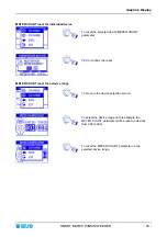
Page 22: ...creens System working in Control status No errors detected At least one WINIDINGFEEDER device running System in STOP status No errors detected All WINIDINGFEEDER devices stopped Error E2 on WINDINGFEEDER 001 device For detailed information about error messages please refer to Section 3 Alternating ...

Page 23: ...s functions the following graphic symbols will be used Turn the selector to point the desired option Select the desired option and click to confirm Press and hold down the button 3 sec to return to previous menu and or to activate the data saving function Error Alternating Error details Main Menu Style configuration Style loading System configuration ...

Page 24: ...d LEDs of all TS44 tension sensors start flashing and the LEDs of Control Enter and Reset buttons toggle red and green In addition the display of all WINDINGFEEDER devices shows the IDENTIFY FEEDER message Press Enter on the First WINDINGFEEDER device and check that a The LED of tension sensor turns off and the LEDs of Control Enter and Reset buttons remain steady green b The display of numbered d...

Page 25: ...isplay Select on the CURRENT field the number of device to be re numbered e g 007 Press Enter on the device you want to assign the number indicated on the CURRENT field e g 007 of SMART MATRIX terminal Check that a The red LED of TS44 tension sensor turns off and the LEDs of Control Enter and Reset buttons remain steady green b the display of numbered device shows the assigned number e g 007 c the...

Page 26: ...ication code to the SMART MATRIX WINDINGFEEDER terminal in case of application that uses multiple terminals Enter the SETUP menu Select MATRIX CODE Choose the SMART MATRIX identification code and activate the save function SAVE to save the choice BACK to return to the previous screen without saving EXIT to return to menu SETUP MATRIX CODE ...

Page 27: ...R manual Enter the SETUP menu Select I O CONFIG Configure the input signals PRX ZPX and STC and the relay output OUT within the SMART MATRIX window the P1 P2 EXC RESET input signals and ALARM TARGET output signals within the WINDINGFEEDER window either as NO or NC For ALARM and TARGET output signals after defining the signal polarity NO NC you have to define even the signal generation mode ALARM M...

Page 28: ...x that will be shown pressing the button The Efficiency Index Calculation function is not currently implemented on SMART MATRIX WINDINGFEEDER application Enter the SETUP menu Select EFFICIENCY Choose either INCLUDED power down times included in the calculation or EXCLUDED To activate the saving function SAVE to save the choice BACK to return to the previous screen without saving EXIT to return to ...

Page 29: ...ist of accessible menus and options it also allows you to remove clear users and to change the list of accessible menus and options You cannot set two users with the same name or with the same password Enter the SETUP menu Select KEY CODE Aggiunta Nuovo Utente Press the indicated button to add a new user Set the new user name e g ALAN and password e g ALAN123 in the ACCOUNT windows Select the menu...

Page 30: ...on Press the indicated button to edit change the access rights of selected user Change the configuration of menus and options available to the selected user SETUP STYLE LOAD STYLE EDIT etc When you try to access a password protected function the following prompt will appear Choose the user name and set the password to access the selected function ...

Page 31: ... Select LINE EFF global communication efficiency or SINGLE communication efficiency with the individual WINDINGFEEDER devices Number of devices on which communication errors occurred DEV IN ERROR and total number of transmission repeated as result of detected errors TOTAL RETRY A maximum of 5 transmission retries are repeated for each device Global efficiency index Number of the selected device 1 ...

Page 32: ...e offset operation Confirm the selection OFFSET to carry out the operation on selected device range BACK to return to previous screen without performing the offset operation EXIT to return to setup menu A temporary OFFSET EXECUTE window will appear then you will have the possibility to select another device range if desired on which to carry out the offset operation We remind that prior to confirm...

Page 33: ...splay of connected WINDINGFEEDER device Enter the SETUP menu Select SERVICE Select LANGUAGE Select the desider language ITALIAN ENGLISH FRENCH SPANISH GERMAN JAPANESE SAVE to save the selection The LANGUAGE SET message indicated that the visualization language on the display of connected WINDINGFEEDER devices is going to change SETUP SERVICE LANGUAGE ...

Page 34: ...unction allows you to view the status of the external interface signal supplied to SMART MATRIX WINDINGFEEDER terminal PRX ZPX STC Enter the SETUP menu Select SERVICE Select I O CHECK This screen page shows the status of the external interface signals IDLE STOP etc To leave the function EXIT to return to SERVICE menu SETUP SERVICE I O CHECK ...

Page 35: ...ontrast of display and to set the display auto off time 1 20 minutes or No Off if the auto off function is not required Enter the SETUP menu Select LCD DISPLAY Adjust CONTRAST BRIGHTNESS DISPLAY AUTO OFF To activate the saving function SAVE to save the settings BACK to return to the previous screen without saving EXIT to return to the menu SETUP LCD DISPLAY ...

Page 36: ... MATRIX WINDINGFEEDER This function allows you to detect the Hardware Firmware OS and Boot Program versions These values shall be communicated to BTSR Service Department when requiring technical support to solve specific problems Enter the SETUP menu Select INFO To return to previous menu SETUP INFO ...

Page 37: ...gn different tension and control parameters to each style in order to meet your specific application needs The STYLE EDIT function requires the programming of 3 sets of parameters in 3 windows PROFILE ADV and CONFIG Programming a new style Select STYLE EDIT Press ADD the indicates that WINDINGFEEDERC is the style currently loaded to the device Parameters Programming within the PROFILE window Setup...

Page 38: ...dow For the explanation of the various parameters please refer to Section 3 Summary table of Style Programming Parameters Parameters Programming within the CONFIG window Setup in sequence the parameters of CONFIG window For the explanation of the various parameters please refer to Section 3 Summary table of Style Programming Parameters ...

Page 39: ... 0 To increase or decrease the selected device correction factor Setting a negative value the TARGET value will be decreased by the set percentage otherwise setting a positive value the TARGET value will be increased by the set percentage SAVE to save the set parameters and move to the STYLE NAME screen Set the style name for instance APPLICATION01 instead of the device name WINDINGFEEDER operatin...

Page 40: ... SMART MATRIX WINDINGFEEDER 28 YES to save the style APPLICATION01 List of styles contained in the database including the APPLICATION01 style To leave the function Programming a New Style EXIT to return to the main menu ...

Page 41: ...tom line of STYLE NAME screen that contains the style name setting keyboard will show the reference name APPLICATION01 instead of the default name WINDINGFEEDER Enter the name to be assigned to the modified style To save the new style If you change the style currently loaded on particular Windingfeeder devices indicated by the diskette symbol the changes will be automatically loaded on the relevan...

Page 42: ... and to view the style map of WINDINGFEEDER devices MAP function Style Load Select the LOAD menu item Choose the style you want to load e g APPLICATION01 and press LOAD Choose the range of devices on which you want to load the style APPLICATION01 Select LOAD A temporary LOADING STYLE window will appear At the end of the loading operation the style list will automatically re appear To leave the fun...

Page 43: ...currently loaded on the devices Confirm the unload operation The style APPLICATION01 will be unloaded from the WINDINGFEEDER devices The diskette symbol will disappear from the right side of the style name Style Map Select the LOAD menu item Press MAP The STYLE column lists the articles styles loaded on the WINDINGFEEDER devices of the machine while the RANGE column lists the device intervals wher...

Page 44: ...ccess to the graphic mode The bar graph indicates number of meters fed METER COUNT by the selected device indicated by the symbol The header bar indicates the percentage value of yarn fed with respect to the set Target in this example 41 To select a new device To move to the dynamic display of tension and speed curves To increase the scale To decrease the scale To indicate either the tension value...

Page 45: ...ted device METER COUNT parameter YES to confirm the reset METER COUNT reset for a device range To move to the device selection screen To select the device range in this example the METER COUNT parameter will be reset on devices from 002 to 004 To reset the METER COUNT parameter on the selected device range ...

Page 46: ...r of detected events on all devices To scroll throughout the alarm list Press this button to clear the counters for the desired device range Press this button to clear the alarm counters for all devices Select the range of devices for which you want to clear the counters To confirm CLR ALL to clear the selected counter range BACK to return to previous screen without clearing the counters EXIT to r...

Page 47: ...Alarm Counter Display SMART MATRIX WINDINGFEEDER 35 To select the desired device FEEDER n To scroll down the alarm list Ø To scroll up the alarm list ...

Page 48: ...Alarm Counter Display SMART MATRIX WINDINGFEEDER 36 Page left intentionally blank ...

Page 49: ...System Information 3 ...

Page 50: ......

Page 51: ...NGFEEDER devices are stationary the CONTROL OK message is replaced by CONTROL STOP The error and failure messages can be classified as follows Errors detected by the SMART MATRIX WINDINGFEEDER power on self diagnostic Error on EEPROM of SMART MATRIX terminal Error on RAM of SMART MATRIX terminal Error on internal communication bus of SMART MATRIX terminal Errors detected on WINDINGFEEDER devices d...

Page 52: ...cessive temperature on the motor of a Windingfeeder device Internal error on a Windingfeeder device Target reached by a Windingfeeder device Supply voltage lower than 15 VDC For detailed information about errors and possible solutions please refer to the Windingfeeder manual ...

Page 53: ...Yarn tension when reaching the TARGET Corresponding parameter of WINDINGFEEDER device Notes In the PROFILE window you may either enable or disable the TENSION PROFILER function i e the dynamic trend of the yarn feeding tension from the machine Startup START TENS up to the Target If you enable the PROFILE option in TENSION MODE then the tension trend will depend on the values set to the remaining p...

Page 54: ...ed P4 4 Corresponding parameter of WINDINGFEEDER device Unlike the TARGET CALIBRATION which can be set for each individual device the K FACTOR parameter is the same for all the involved devices Setting a negative value the TARGET value will be decreased by the set percentage otherwise setting a positive value the TARGET value will be increased by the set percentage Parameters programmable on CONFI...

Page 55: ...l have the possibilità of programming the desired tension trend trought all the parameters of PROFILE window Application Examples Based on Tension Profiler Function 1 Tension Profiler Function Disabled TENSION MODE P1 P2 You may setup only the following values WORK TENS P1 0 2 to 99 5 g WORK TENS P2 0 2 to 99 5 g or OFF INC DEC TENS It can be handled with external Inc Dec commands only TARGET METE...

Page 56: ...rameter setup in the PROFILE window START METER 200 START TENS 2 WORK TENS 5 INC DEC METER OFF TARGET METER OFF In both cases whenever a position is stopped for more than 3 seconds for instance after a yarn breakage condition the system will resume the START TENS and will return to the normal WORK TENS after the number of meters defined in START METER 3 Tension Profiler Enabled with Target Activat...

Page 57: ...ension Profiler Function Enabled with TARGET and INC DEC METER Activated With respect to the previous example we now introduce a further item INC DEC TENS used to graduate the WORK TENS with the timing established in INC DEC METER This allows you to dynamically change the work tension with constant increment decrement steps in such a way as to obtain a package compliant with the specific requireme...

Page 58: ...sion Profiler SMART MATRIX WINDINGFEEDER 46 Exsample 2 of parameter setup in the PROFILE window START METER 200 START TENS 3 WORK TENS 6 INC DEC METER 2000 INC DEC TENS 0 1 TARGET METER 50000 TARGET TENS 2 ...

Page 59: ...BTSR International S p A Via S Rita 21057 OLGIATE OLONA VA Tel 0331 323202 Fax 0331 323282 Internet www btsr com REV 1 2 02 12 DISTRIBUTORE ...

Reviews: