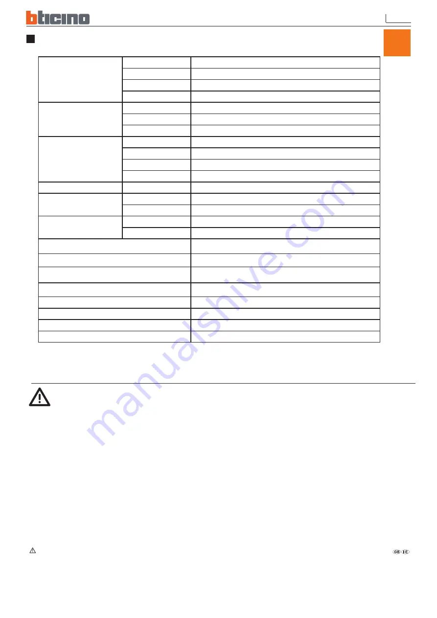
background image

13

SPECIFICATION

Video

Format

PAL

Compression

MJPEG

Input

4 CH, BNC 

Output

1 CH BNC

Display

Resolution

720x576 (PAL) 

Frame Rate

Max. 100 IPS

Division

Single, Quad

Recording

Resolution

640x272 (PAL) 

Frame Rate

Max. 50 IPS

Quality

High / Normal / Low

Mode

Manual / Schedule / Motion Detection

HDD

Basic storage

1x3.5” SATA - 320 Gb

Alarm

Triggered Mode

Motion Detection, Video Loss

Action

Recording, Sound Alert

Audio

Input

1CH, RCA 0,5-1 Vpp @ 20 kohm

Output

1CH, RCA

Backup Device

USB

Post Alarm

1 ~ 60sec

Search Method

By Date, Time, Event

Power Supply

AC100~240V 50/60 Hz, DC12V / 2.5A

Weight 

2.9 kg 

Dimensions (WxHxD) 

195X45X226mm 

Operating Environment

30 ~ 80% RH, 5°C ~ 40°C

Remote Control

IR Transmission

-  The installation and calibration must be carried out by highly skilled personnel.

- Do not open there may be a risk of electric shock.

Use only for the following temperature conditions: from (+5) to (+40) °C.

Do not use with voltages different from the ones specified.

Warning

       Safety instructions

This product should be installed in line with installation rules, preferably by a qualified electrician. Incorrect installation and use can lead to risk of electric shock or fire.

Before carrying out the installation, read the instructions and take account of the product’s specific mounting location.

Do not open up, dismantle, alter or modify the device except where specifically required to do so by the instructions. All Bticino products must be opened and repaired exclusively by personnel trained and 

approved by Bticino. Any unauthorised opening or repair completely cancels all liabilities and the rights to replacement and guarantees.

Use only Bticino brand accessories.

UK

Summary of Contents for 391504

Page 1: ...Part LE03093AA 4CH MJPEG DVR Instructions manual 391504 MANUALE DI ISTRUZIONI USER MANUAL Part LE03092AA DVR 4 INGRESSI 4 CHANNELS DVR ...

Page 2: ......

Page 3: ...eratura da 5 a 40 C Non utilizzare con tensioni differenti da quelle specificate L utilizzo di questo prodotto deve essere fatto nel rispetto delle norme vigenti sia in materia di privacy d lgs n 196 2003 sia di tutela dei lavoratori l 300 1970 Statuto dei lavoratori Attenzione Istruzioni di sicurezza Questo prodotto deve essere installato in conformità con le regole d installazione e di preferenz...

Page 4: ...zione ingresso AC 100 240V Uscita DC 12V 2 5A 1 Cavo di alimentazione 1 CD ROM 1 Manuale d installazione rapida 1 Telecomando 1 Assicurarsi che tutti i prodotti di seguito indicati siano presenti nella confezione Se qualcosa manca contattate il vostro rivenditore non appena possibile DISTINTA DI SPEDIZIONE ...

Page 5: ...selezione Pulsante direzione sinistra display schermo canale 2 Pulsante direzione alto display schermo canale 1 Pulsante direzione destra display schermo canale 4 Invio Uscita Menu Pulsante direzione basso display schermo canale 3 Pulsante Registra Stop Pulsante Play Pausa LED indicatore di accensione IR Sensor 1 2 3 4 5 6 7 8 9 10 11 12 ...

Page 6: ... IN Collegamento alle videocamere 3 Uscita Video VIDEO OUT Collegamento al monitor 4 Ingresso Audio AUDIO IN Porta ingresso RCA per segnale audio 5 Uscita Audio AUDIO OUTPUT Porta uscita RCA per segnale audio 6 USB Collegamento a un dispositivo di archiviazione USB esterno Plug and Play 7 VGA uscita segnale VGA ...

Page 7: ...scita video VGA INSTALLAZIONE Configurazione del sistema Collegare al dispositivo di archiviazione USB Remarque Nota 1 è consigliabile non utilizzare un cavo di prolunga più lungo di 60 cm 2 Rimuovere il dispositivo USB solo dopo che il processo di identificazione è stato completato Collegare all INGRESSO VIDEO del Monitor LCD Collegare all INGRESSO VIDEO del Monitor Linea di segnale Video USCITA ...

Page 8: ...essaggio ID TELECOMANDO CORRETTO la funzione di sincronizzazione delle impostazioni è completa E possibile ora controllare il DVR dal telecomando 4 Ogni volta la sincronizzazione permette che un singolo dispositivo sia controllato da un singolo telecomando Instruzioni per gestione del codice ID del telecomando Entrare nel MENU e selezionare la voce ID telecomando per impostare l ID del telecomando...

Page 9: ...ante per avviare la riproduzione premere il pulsante per entrare nella schermata di menu configurazione Durante la riproduzione premere il pulsante per tornare alla modalità monitoraggio In modalità Registrazione Manuale premere il pulsante per interrompere la registrazione e tornare in modalità monitoraggio o premere il pulsante nel menu principale per tornare sempre alla modalità monitoraggio Du...

Page 10: ...PENTI Canale 3 Lo schermo blu indica una perdita video M Il simbolo M indica registrazione manuale Il simbolo S indica registrazione programmata Quando sia la registrazione manuale che programmata sono attive la registrazione manuale verrà visualizzata per prima Registrazione in corso Rilevazione movimento HDD sta sovrascrivendo i dati ...

Page 11: ...ario premere il pulsante MENU p er tornare alla schermata Ricerca Orario e premere il pulsante Play di nuovo per visualizzare l orario selezionato 3 Durante la riproduzione premere il pulsante per mettere in pausa e premere di nuovo per avviare la riproduzione 4 Premere il pulsante per andare avanti velocemente e il pulsante per andare indietro 5 Premere il pulsante per fermare la riproduzione ...

Page 12: ......

Page 13: ...carried out by highly skilled personnel Do not open there may be a risk of electric shock Use only for the following temperature conditions from 5 to 40 C Do not use with voltages different from the ones specified Warning Safety instructions This product should be installed in line with installation rules preferably by a qualified electrician Incorrect installation and use can lead to risk of elec...

Page 14: ...NG LIST 5 3 PACKING LIST Check to make sure all of the items shown below are included in your product package If something is missing contact your dealer as soon as possible e r u t c i P m e t I n o i t p i r c s e D m e t I QTY DVR 1 DC 12V 2 5A Power Adapter Input AC 100 240V Output DC 12V 2 5A 1 Power Cord 1 CD ROM 1 Quick Installation Guide 1 Remote Control 1 ...

Page 15: ...basso display schermo canale 3 9 Pulsante Registra Stop 10 Pulsante Play Pausa 11 LED indicatore di accensione 12 IR Sensor LED indicatore di registrazione Pulsante indietro Pulsante avanti veloce Invio selezione Pulsante direzione sinistra display schermo canale 2 Pulsante direzione alto display schermo canale 1 Pulsante direzione destra display schermo canale 4 Invio Uscita Menu Pulsante direzio...

Page 16: ...VIDEO IN Connect to cameras 3 Video Output VIDEO OUT Connect to the monitor 4 Audio Input AUDIO IN RCA input port for an audio signal 5 Audio Output AUDIO OUTPUT RCA output port for an audio signal 6 USB Connect to external USB storage device Plug and Play 7 VGA VGA signal output ...

Page 17: ...ction by following the illustration shown below Connect camera monitor and power to enter monitoring mode To backup images connect the USB storage device The DVR also supports VGA video output INSTALLATION System configuration ...

Page 18: ...ng mode Because the setup is only effective if you return to LIVE mode after the setup 3 After returning to LIVE monitoring mode press remote control CHECK ID ALL 11 12 21 22 23 31 32 33 to confirm synchronization When the message REMOTE ID IS CORRECT appears indicate synchronize function setup is complete Now you are able to control the DVR using remote control 4 Each time synchronization allows ...

Page 19: ...s button the system enters the manual record mode press button to start playback press button to enter the menu setup display During playback press button to return to monitoring mode Under Manual Record mode press button to stop recording and return to monitoring mode or press MENU button under main menu also returns to monitoring mode During playback press Stop button to return to monitoring mod...

Page 20: ... OFF CH3 Blue screen indicates video loss M Symbol M indicates manual recording Symbol S indicates schedule recording When both manual and schedule recording has been enabled Currently under recording Motion event detected Video input unable to be detected video loss has occurred HDD is overwriting data ...

Page 21: ...up mode After time setup has been completed press MENU button to return to Time Search display and press Play button again to playback the selected time 3 During playback press button to pause and press again to playback 4 Press button to fast forward playback and button to rewind 5 Press button to stop playback ...

Page 22: ......

Page 23: ......

Page 24: ......

Reviews: