


BALANCE
Your R54 must balance in the range shown on the plans, with the UAT full of fuel (since it is behind the CG) and the
gear retracted. Do not exceed the rear limit! In general, it easiest to balance the R54 upside down. Most likely, you
will need to add some lead to the nose. The nose block cavity will hold a fair amount of lead shot, but you may need
even more. Every modeler hates to add dead weight, but grit your teeth and add enough to be in the forward half of
the balance range for the first flight. You can put lead shot in small plastic bags which can be removed later as
desired. Be sure to also check the lateral balance and add weight to one of the wingtips if necessary to balance.
CONTROL THROWS
Adjust the amount of control surface deflection to the amounts shown below. These are fairly active settings - go easy
on the sticks for the first flight or two, then adjust the control throws to suit your flying style.
RECOMMENDED CONTROL THROWS
AILERONS:
3/4" UP, 5/8" DOWN
ELEVATOR:
5/8" UP, 5/8" DOWN
RUDDER:
1-1/2" LEFT, 1-1/2" RIGHT
FLAP DEFLECTION:
FULL MOVEMENT (60°)
DOWN ELEVATOR WITH FULL FLAPS:
1/8"
Notice the ailerons should move UP more than DOWN. This aileron differential helps combat adverse yaw, making for
smoother rolls. If you like rates or exponential, but go ahead and program them in if you wish.
Automatic DOWN
elevator compensation is helpful to counteract the nose-up tendency of the model when the flaps are deployed. This
is a common feature found on many modern radios.
PRE-FLIGHT INSPECTION
Be sure to perform radio range checks, both with the turbine off AND
with it running. If there is a significant decrease in the range with the
engine running, you may need to reposition your components or re-
route the antenna. Keep in mind that even though this is a big
airplane, it's the little things that will "getcha". Double check all of your
servo arm screws, clevises, pushrods, nuts, bolts, hinges, cables, and
fuel tank connections. Triple check that your flight controls are all
moving in the proper direction.
AN IMPORTANT SAFETY NOTE
You also need a positive way of shutting off the engine from the
transmitter, either using full idle trim or a separate channel to switch off
the turbine instantly. If you have any trouble during flight, the most
important thing you can do as a pilot is to shut off the turbine
without
hesitation.
The chance of a post-crash fire is greatly diminished if you
get the turbine shut down before impact. With its huge wing, the R54
can glide in for a safe landing from nearly anywhere if you still have
control (a nice feature for flameouts - believe me!).
R54
33
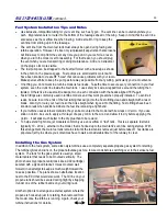
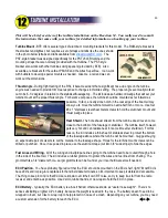
Start Tube
- I consider it mandatory to use
some sort of flame protection for the model
during every turbine start up. A hot start could
obviously cause a problem, but even normal
starts often produce a small flame and hot,
slow-moving exhaust gases that can scorch
Monokote. I use this start tube made from
double-walled stovepipe with plywood legs.
Notice the hinged extension at the bottom of the
front plywood leg. The height can be changed
so it works with both my R54 and my PST
Reaction ARF. Warn helpers to grab the
plywood after starting - the tube will be hot!
Summary of Contents for Reaction 54
Page 1: ...INSTRUCTION BOOK...