background image

19

• 

Now gradually rotate the 

threshold

 control anti-clockwise. At some position

you will hear your signal appear - the gate has now ‘opened’. Notice also that
the green 

open

 light has come on. Spend a few minutes adjusting the

threshold control and watching the display.

 Depress the 

depth

 switch whilst listening to the program. Notice that with

the switch in, the signal does not completely disappear when the gate is
‘shut’. The most appropriate setting for this switch will depend very much on
the specific application. For general noise reduction on background
microphone clutter, the 20dB position sounds less obtrusive.

 The 

attack

 switch and 

release

 control can be intuitively operated. 

Attack

 is

the time taken for the gate to open once the threshold level has been reached.
The 

release

 is the time taken for the gate to fully close once the 

hold

 cycle

has finished. On the DPR 944, the hold time varies with the setting of the

release

 control, being set internally to about 20% of the selected release time.

Take some time to experiment with these controls to hear their effects on the
envelope of the program signal. Whilst doing this also observe how the gate

open

 and 

shut

 lights fade between each other, precisely following the sound.

You will notice that these follow the actual times set by the 

attack

 and

release

 controls, and is a true indication dynamically of the state of the gate.

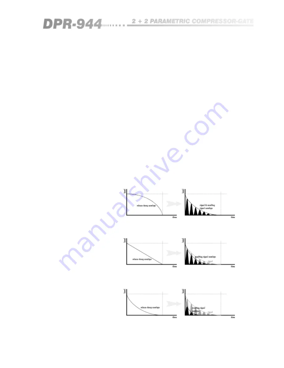
BSS use the release characteristic of 

figure 7.3a

, the aim being to effect the

natural decay of the signal as little as possible initially, whilst providing a
rapid reduction as the signal decays toward the noise 

(see figure 7.3b)

.

Fig 7.3a&b Most

unobtrusive release -

the BSS technique

Figure 7.4a

 shows a compromise solution. Here the signal is reduced linearly,

but as can be seen in 

figure 7.4b

, there is some modification of the signal.

Fig 7.4a&b

Compromise release

Figure 7.5a

 shows the easiest (and worst) implementation of gating. As shown

in 

figure 7.5b

, when applied to a decaying signal, the result is an abrupt

reduction which sound unnatural.

Fig 7.5a&b Most

synthetic release

This covers the basic operation of the DPR 944. For a more detailed
description of the controls, please 

refer to section 6.0

. For information

covering specific configurations, please 

see section 8.0

.

Summary of Contents for DPR-944

Page 1: ...1 DPR 944 User Manual...

Page 2: ...at all input and output cables are wired with the cable screen connected to Pin 1 of the XLR connectors and or the jack plug sleeve The input XLR Pin 1 and the side chain input jack socket sleeve are...

Page 3: ...In 12 6 2 Key filter 12 6 3 Filter narrow 12 6 4 Key listen 13 6 5 Threshold 13 6 6 Depth 20dB 14 6 7 Attack slow 14 6 8 Release 15 6 9 Stereo link 15 6 10 Open Shut LEDs 16 6 11 Key insert connector...

Page 4: ...ect of compression limiting on sound 30 10 4 Frequency selective compression 31 11 0 Application examples Compressors 32 11 1 Broadband normal compression 32 11 2 Peak limiting 32 11 3 De essing De po...

Page 5: ...ont mounting flange The necessary support can generally be bought ready built as a rack tray or the DPR 944 can be mounted between other units Damage caused by insufficient support is not covered by t...

Page 6: ...de Green and Yellow Earth Blue Neutral Brown Live Those units supplied to the North American market will have an integral moulded 3 pin connector which is provided to satisfy required local standards...

Page 7: ...ring and to ensure that it is possible to use a fast attack time without running into the problem of jittering The provision of fully parametric key filtering and an external key input adds to the eas...

Page 8: ...8 The DPR 944 Fig 4 2 Rear Panel Fig 4 1 Front Panel...

Page 9: ...9 All numbers in bubbles refer to Section numbers...

Page 10: ...formance The screen of the input cable should be connected to pin 1 to ensure that EMC regulations are being met and the cable shield ground should also be connected to the equipment which is providin...

Page 11: ...nnection between the side chain filter output and gate threshold input allowing further side chain processing or external triggering When using the DPR 944 to drive unbalanced inputs best performance...

Page 12: ...ignal is present on the output In bypass mode switch out the input is still connected to the DPR 944 circuitry so that all of the required facilities can be selected and set up prior to operating the...

Page 13: ...6 4 Key listen When this switch is depressed it connects the output of the key filter to the output connector instead of the normal signal This makes it very easy to adjust the key filter and filter n...

Page 14: ...ld the gate will start to open The time it takes to open is determined by the attack switch For conventional gating the fast attack switch out position is usually desired to ensure that the minimum wa...

Page 15: ...is reduced as in figure 7 3b This produces a very natural sounding fade because the normal dynamics of the signal are preserved which is especially important for long release times 6 9 Stereo link Wit...

Page 16: ...may appear as though nothing happens for a while What is in reality happening is that the sound and lights are fading but the lights are initially fading too slowly to be noticable 6 11 Key insert con...

Page 17: ...ny other way The other called the key signal is processed to provide a trigger for the switch Once the main signal has exceeded the user selected threshold and provided the trigger the gate will open...

Page 18: ...the first noise gates General guide to gating 7 2 Basic operation These instructions are primarily designed to help you get started using the DPR 944 The left hand part of the front panel is split in...

Page 19: ...with these controls to hear their effects on the envelope of the program signal Whilst doing this also observe how the gate open and shut lights fade between each other precisely following the sound Y...

Page 20: ...pped up Adjusting the attack and release controls will change the nature of the sound You may find that certain settings of these controls never allow the gate to close Set the threshold so that the g...

Page 21: ...the beat notes are prominent When you are happy with the filter controls release the key listen switch Now adjust the threshold control you should now hear the beats in the program Experiment with the...

Page 22: ...n be selected and set up 9 2 Threshold This control sets the signal level that is required to invoke compressor operation If a signal is below threshold the DPR 944 will not compress it although the g...

Page 23: ...upt manner as shown in figure 9 2 The DPR 944 has been configured so that for low settings of the ratio control and low levels of compression the transfer is soft and for increasing ratio settings and...

Page 24: ...lease to avoid rapid gain change effects Operation with the release fast switch out will cater for the vast majority of applications providing a very unobtrusive musical compression If the release tim...

Page 25: ...main compressor output of the unit from the normal compressor output and connects it instead to the output of the parametric filter controlled with the width and frequency controls This allows the fi...

Page 26: ...oth compressor 1 and compressor 2 together so that both channels respond equally to the largest signal present This combined signal is passed through the side chain filter threshold ratio release and...

Page 27: ...is a useful way of expressing compressor action as it gives an instantaneous indication of how much the signal is actually being processed If for example a particular signal transient exceeds the thr...

Page 28: ...transient loudness peaks present in program material The safety margin is known as headroom and is generally in the range of 10 to 20dB Lowering the standard operating level to increase headroom help...

Page 29: ...he threshold level Any program level in excess of the threshold will immediately be reduced to this threshold level A compressor will also continuously monitor the program and has a threshold level Ho...

Page 30: ...ide to compressing Comparing the input and output waveforms for the compressed mode the loudest portions of the signal have been effectively decreased in level and if the gain control is adjusted to c...

Page 31: ...ast switch should generally be out 10 4 Frequency selective compression As described above conventional compressors affect the whole audible band of frequencies equally Some compressors can be configu...

Page 32: ...am related dynamics adjustment that will be acceptable for most general purpose applications Should a tighter sound be required depress the fast release switch The experienced engineer will be able to...

Page 33: ...to 3 o clock notice that when a sibilant sound is encountered the gain reduction meter starts to indicate The frequency width threshold and ratio controls can now be fine tuned to achieve the desired...

Page 34: ...ng but set the frequency control to select low frequencies Fig 11 3 De popping a signal Also concerning microphones and affecting the bass end of the band is the proximity effect which causes the low...

Page 35: ...e but at lower frequency and narrower width settings is very useful for levelling the signal from a bass guitar Quite often either due to technique or the instrument particular notes will be a great d...

Page 36: ...other Try this with different width settings and don t forget to let us at BSS Audio know about any unusual applications you may find With some program playing depress the side chain listen switch By...

Page 37: ...in the European Union you may as an alternative return the unit to any other BSS distributor in the European Union You should include a statement listing the faults found The unit s serial number must...

Page 38: ...ents 25 of release time setting Compressor General InputImpedance 10k Ohms balanced or unbalanced InputCMRR 40dB30Hz 20kHz Output level 20dBu into 600 Ohms or greater OutputImpedance 50 Ohms balanced...

Page 39: ...26 Threshold 22 Width 26 Comps in 22 Connections audio 10 Creative use 36 D De essing 33 De popping 33 Depth 20dB 14 Dimensions 5 E Effect of compression on sound 30 F Filter narrow 12 Frequency 25 Fr...

Page 40: ...ting 32 Proximity effect reducing 33 R Rack dimensions 5 Ratio 23 Rear Panel 8 Release 15 Release fast 24 S Shut LED 16 Side chain filter use as EQ 36 Side chain listen 25 Specifications 38 Stereo lin...

Page 41: ...41 User Notes...

Page 42: ...4 2 User Notes...

Reviews: