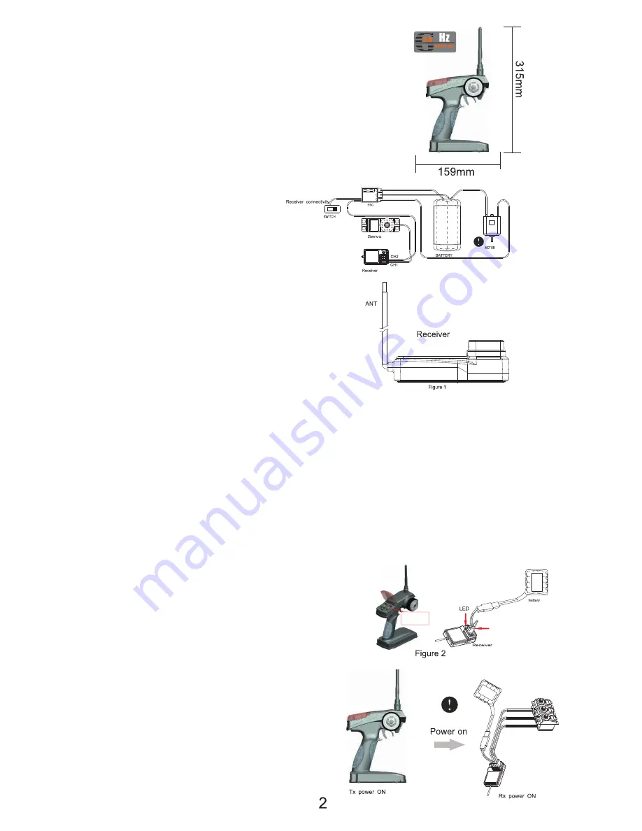
Channels : 2
Model Type : Car/Boat
Frequency : 2.4GHz
Power :12V DC (8 x AA batteries)
Charging Port : Built-in (centre pole +)
Low Voltage Warning : Yes (below 9V)
Transmitter Specifications:
The antenna on the receiver must be
positioned vertically to achieve optimum
range(Figure 1).It must be kept away from
any metallic or carbon components.
Note:
Your Century UK-BSD car features a quality 2.4 GHz radio control system. Under normal circumstances it is
virtually immune to interference from other radio controlled models. All 2.4GHz systems are required to
undergo a process called “binding”. This is where a receiver is programmed only to respond to commands
from one unique transmitter. The binding process has already been carried out at the factory by default.
Under certain circumstances it may be necessary for a 2.4GHz system to require a re-bind. In this event,
please refer to the following instructions.
Transmitter Operation:
1. Ensure you have fresh batteries installed in the transmitter.
2. Insert the “bind-plug” into the port on the receiver marked: CH3. (Figure 2).
3. Connect a receiver battery (4.8V DC) to the receiver port marked VCC. The two LEDs on the receiver will flash
rapidly, indicating that it has entered the binding mode.
4. Press and hold the bind button on the transmitter, and simultaneously turn on the power switch.Note: The
bind button is recessed to prevent accidental operation.
5. Continue to hold the bind button. After approx. 5
seconds the receiver LEDs will stop flashing, indicating
that binding has taken place.
6. Release the bind button on the transmitter and remove
the binding plug from the receiver.
7. Connect the steering servo to the receiver and operate
the steering function on the transmitter to test the system.
8. If the test is successful, remove the power supply from
the receiver port marked VCC.
9. The binding process is now complete.
Binding:
When operating the model, always comply
with the following procedure:
1. Turn on the power switch on the transmitter first.
2. Connect the power supply to the receiver.
3. The receiver LED should illuminate without flashing.
4. Follow engine starting procedure.
Turn On:
Bind Button
Bind Plug


