5
If a valve is set to a higher pressure than the original
set pressure, the rupture of the spring could occur and
a reduction of the distance between the spring coils,
limiting the valves opening, and therefore, the relief
flow would decrease. The “blowdown” would increase.
If set pressure is decreased, would be increased
overpressure in the installation.
Before increasing the set pressure of already installed
valve, be sure to verify that the new pressure is inside
the nominal pressure range it is been designed for.
Also, before decreasing the set pressure, it needs to
be verified that required capacity with new set
pressure is going to be enough to protect the container
it is been for.
4.1 HYDROSTATIC TESTS
When the hydrostatic test of a container is required, it
must be ensured that the safety-relief valve would not
deteriorate.
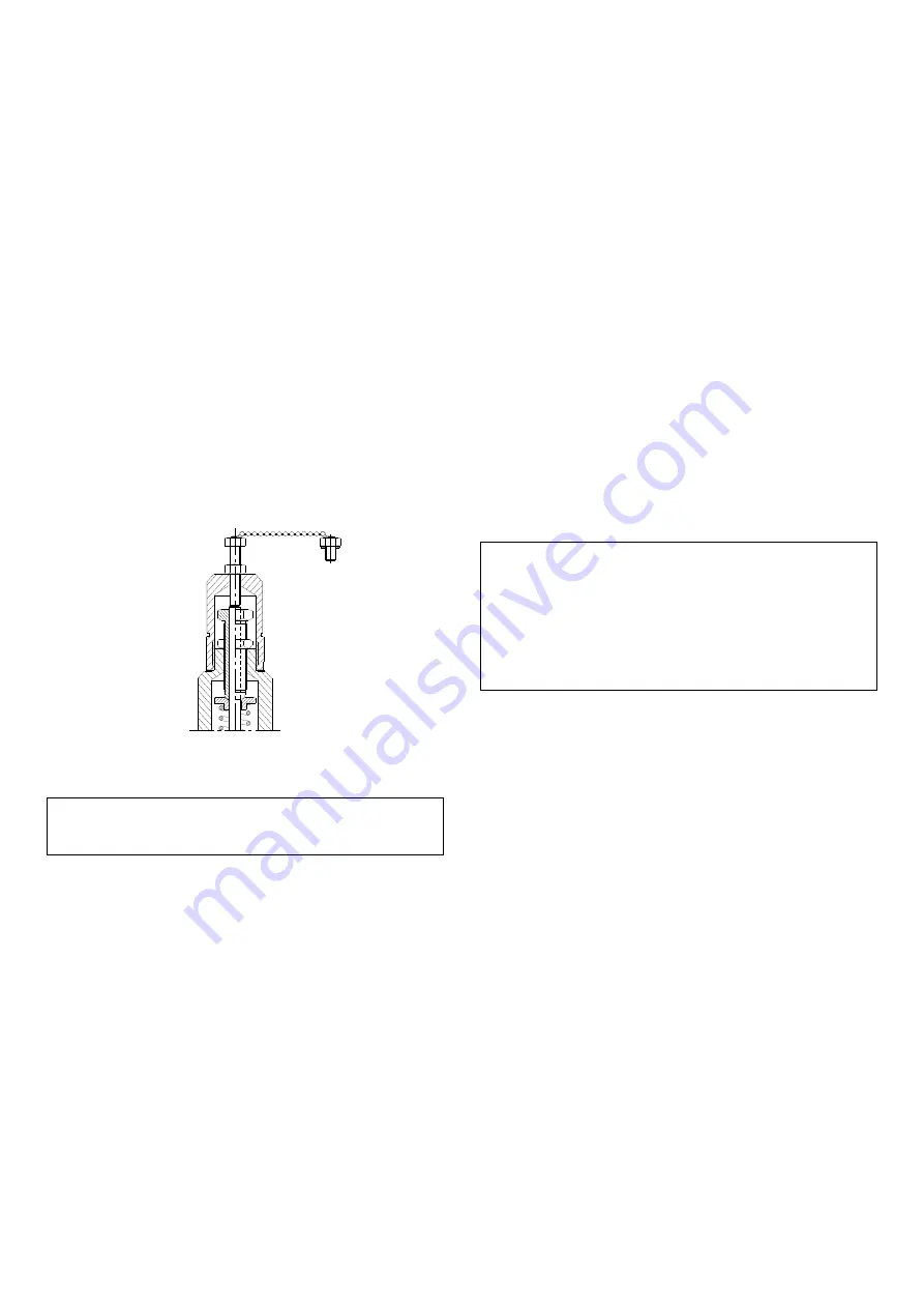
When making the test upstream, the valve needs to be
nullified, installing the test-gag in order to avoid its
opening.
TEST-GAG
Once the hydrostatic test is finished, the lock
screw needs to be replaced, otherwise the safety-
relief valve would remain completely voided.
When the hydrostatic test is performed upstream, it
has to be checked that the pressure that the valve will
receive does not exceed the limitations of its design,
mainly in those valves including bellows.
4.2 BLOWDOWN ADJUSTMENT
The blowdown pressure regarding the set pressure at
the closing moment of the valve after the popping can
be “adjusted” using the adjusting ring (7) mounted over
the nozzle (4). (Check the drawing in page -8-).
In case the blowdown value should be adjusted, once
the valve is assembled in the installation, proceed as
follows:
- Unscrew the screw (14) which fixes the adjusting ring
(7).
- Using a screwdriver turn the adjusting ring upwards
until making contact with the disc holder (8), then turn
it to the opposite direction so many grooves as Table 1
points out.
- In order to increase the blowdown (the valve will
close itself at a very low inlet pressure) the adjusting
ring has to be risen turning the grooves counter
clockwise (from left to right).
- To decrease the blowdown (the valve will close itself
at a very high inlet pressure) the adjusting ring has to
be lowered turning the grooves clockwise (from right to
left).
- Once the adjusting ring has been adjusted, the lock
screw has to be assembled back, checking that the
stud remains placed inside the adjusting ring‘s groove,
fixing it to keep it from spinning, but free for its
alignment.
5 - MAINTENANCE
If the valve has been working at an installation with
fluids classified as dangerous or pollutant,
decontamination has to be performed prior to its
manipulation.
It is highly important to follow the disassembly
sequence as described below, as any alteration
may be dangerous for the worker who is
manipulating the valve, due to the spring tension.
To achieve a correct valve operation, the use of
original spare parts is essential.
5.1 ASSEMBLY AND DISASSEMBLY - VALVE 3-
5111
To perform the assembly and disassembly operations
check valve section drawings in page -8-.
5.1.1
DISASSEMBLY
Unscrew the cap (3).
If the valve has a lever, disassemble the lever (59),
unscrew the holder (62) and unscrew the cap (53).
Once the position of the release nut (43) is checked by
measuring distance between the top side and the edge
of the stem, loosen the capture (44) and disassemble
it.
Before losing the spring (11), write down the distance
between the top part of it to the edge of the stem. This
will allow to place it in the same position assembled.
Unscrew the adjusting nut (13) and the adjusting screw
(11) until all the tension in the spring is freed (10).


