


577C--C, 577C--E, 577C--F: Installation Instructions
Manufacturer reserves the right to change, at any time, specifications and designs without notice and without obligations.
27
Gas Heating Fan Speed Set-up (3 Phase Models)
To change the gas heating speed:
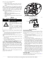
1. Remove the vinyl cap off of the desired speed tap wire (Refer to
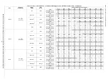
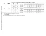
temperature rise associated with each fan speed for a given static
pressure. Make sure that the speed chosen delivers a temperature
rise within the rise range listed on the unit rating plate.
2. Remove the current speed tap wire from the “GAS HEAT” terminal
on the interface fan board (IFB) (
) and place vinyl cap over
the connector on the wire.
3. Connect the desired speed tap wire to the “GAS HEAT” terminal on
the interface fan board (IFB).
Cooling Fan Speed Set-up (Dehumidification
feature not used) (Single Phase Models):
To change cooling speed:
1. Remove existing speed tap wire from the “COOL” terminal on the
IGC board. Add the wet coil pressure drop in
static to determine the correct cooling airflow speed in
will deliver the nominal cooling airflow listed in
size.
2. Connect the desired speed tap wire on the “COOL” terminal on the
IGC board.
Single Cooling Fan Speed Set-up
(Dehumidification feature not used) (3 Phase
Models)
To change cooling speed:
1. Remove the vinyl cap off of the desired speed tap wire (Refer to
for color coding). Add the wet coil pressure drop in
to the system static to determine the correct cooling
airflow speed in
that will deliver the nominal
for each size.
2. Remove the current speed tap wire from the “LOW” terminal on the
interface fan board (IFB) (See
) and place vinyl cap over the
connector on the wire.
3. Connect the desired speed tap wire to the “LOW” terminal on the
interface fan board (IFB).
Dehumidification Cooling Fan Speed Set-up
(Single Phase Models):
IMPORTANT:
Dehumidification control must open control circuit on
humidity rise above set point.
Use of the dehumidification cooling fan speed requires use of either a 24
VAC dehumidistat or a thermostat which includes control of a 24 VAC
dehumidistat connection. In either case, the dehumidification control
must open the control circuit on humidity rise above the
dehumidification set point.
1. Move shunt jumper on IGD board to “DH” (See
).
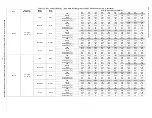
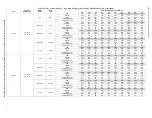
2. Refer to airflow table (
) to determine allowable speeds for
the dehumidification cooling fan speed. Speeds that are not allowed
are shaded in
.
3. Connect selected speed tap wire to “DHUM” terminal on the IGC
board. Verify that static pressure is in the acceptable range for the
speed tap to be used for dehumidification cooling.
Two Cooling Fan Speeds Set-up
(Dehumidification feature used) (3 Phase Models)
IMPORTANT:
Dehumidification control must open control circuit on
humidity rise above set point.
Use of the dehumidification cooling fan speed requires use of either a 24
VAC dehumidistat or a thermostat which includes control of a 24 VAC
dehumidistat connection. In either case, the dehumidification control
must open the control circuit on humidity rise above the
dehumidification set point.
1. Remove fan speed tap wire from the “LOW” terminal on the
interface fan board (IFB) (See
).
2. Determine correct normal cooling fan speed for unit and
application. Add the wet coil pressure drop in
to the
system static to determine the correct cooling airflow speed in
that will deliver the nominal cooling airflow as
3. Remove the vinyl cap off of the desired speed tap wire (Refer to
for color coding) for the normal cooling fan speed and place
desired speed tap wire on “HIGH” on the interface board.
4. Refer to airflow tables (
or
) to determine
allowable speeds for the dehumidification cooling fan speed. In
speeds that are not allowed for
dehumidification cooling are shaded.
5. Remove the vinyl cap off of the desired speed tap wire (Refer to
for color coding) for the dehumidification cooling fan speed
and place desired speed tap wire on the “LOW” connection on the
interface board (IFB). Verify that static pressure is in the acceptable
range for the speed tap to be used for dehumidification cooling.
6. Use any spare vinyl plugs to cap any unused speed tap wires.
NOTE:
For cooling operation, the recommended airflow is 350 to 450
CFM for each 12,000 Btuh of rated cooling capacity.
Continuous Fan Speed Set-up (Single Phase
Models):
To change continuous fan speed:
1. Remove existing speed tap wire from the “FAN” terminal on the
IGC.
2. Connect the desired speed tap wire on the “FAN” terminal on the
IGC board.
Continuous Fan Operation (3 Phase Models)
When the DEHUM feature is not used, the continuous fan speed will be
the same as cooling fan speed. When the DEHUM feature is used, the
continuous fan will operate on IFB “LOW” speed when the DH control
lead is not energized, or IFB “HIGH” speed when the DH lead is
).
Cooling Sequence of Operation
With the room thermostat SYSTEM switch in the COOL position and
the FAN switch in the AUTO position, the cooling sequence of operation
is as follows:
1. When the room temperature rises to a point that is slightly above
the cooling control setting of the thermostat, the thermostat
completes the circuit between thermostat terminal R to terminals Y
and G.
2. The normally open contacts of energized contactor (C) close and
complete the circuit through compressor motor (COMP) to
condenser (outdoor) fan motor (OFM). Both motors start instantly.
3. The set of normally open contacts on the interface fan board (IFB)
are closed which energizes a circuit to the indoor fan motor (IFM).
NOTE:
Once the compressor has started and then stopped, it should not
be started again until 5 minutes have elapsed. The cooling cycle remains
on until the room temperature drops to a point that is slightly below the
cooling control setting of the room thermostat. At this point, the
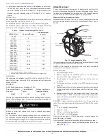
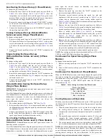
Table 8 – Color Coding for Indoor Fan Motor Leads
Black = High Speed
Orange = Med-High Speed
Red = Med Speed
Pink = Med-Low Speed
Blue = Low Speed