


1
577D----A
EVOLUTION
R
15 SEER SINGLE--PACKAGED AIR CONDITIONER AND GAS FURNACE
SYSTEM WITH PURON
R
(R--410A) REFRIGERANT
SINGLE PHASE
2--5 NOMINAL TONS (SIZES 24--60)
Installation Instructions
EQUIPMENT OPERATION HAZARD
Failure to follow this caution may result in improper unit
operation.
OAT sensor must be field installed. See Accessory
Installation for more details.
CAUTION
!
EQUIPMENT OPERATION HAZARD
Failure to follow this caution may result in improper unit
operation.
This Evolution
r
unit is designed for use with an Evolution
User Interface.
CAUTION
!
NOTE
:
Read the entire instruction manual before starting the
installation.
TABLE OF CONTENTS
PAGE
SAFETY CONSIDERATIONS
2
. . . . . . . . . . . . . . . . . . . . . . . . .
INTRODUCTION
2
. . . . . . . . . . . . . . . . . . . . . . . . . . . . . . . . . . .
RECEIVING AND INSTALLATION
2--13
. . . . . . . . . . . . . . . . .
Check Equipment
2
. . . . . . . . . . . . . . . . . . . . . . . . . . . . . . . . . .
Identify Unit
2
. . . . . . . . . . . . . . . . . . . . . . . . . . . . . . . . . . . .
Inspect Shipment
2
. . . . . . . . . . . . . . . . . . . . . . . . . . . . . . . . .
Provide Unit Support
2
. . . . . . . . . . . . . . . . . . . . . . . . . . . . . . .
Roof Curb
2
. . . . . . . . . . . . . . . . . . . . . . . . . . . . . . . . . . . . . .
Slab Mount
3
. . . . . . . . . . . . . . . . . . . . . . . . . . . . . . . . . . . . .
Provide Clearances
3
. . . . . . . . . . . . . . . . . . . . . . . . . . . . . . . . .
Rig and Place Unit
3
. . . . . . . . . . . . . . . . . . . . . . . . . . . . . . . . .
Inspection
3
. . . . . . . . . . . . . . . . . . . . . . . . . . . . . . . . . . . . . .
Rigging/Lifting of Unit
9
. . . . . . . . . . . . . . . . . . . . . . . . . . . .
Select and Install Ductwork
9
. . . . . . . . . . . . . . . . . . . . . . . . . . .
Configuring Units for Downflow (Vertical) Discharge
10
. . .
Provide for Condensate Disposal
10
. . . . . . . . . . . . . . . . . . . . .
Install Flue Hood
11
. . . . . . . . . . . . . . . . . . . . . . . . . . . . . . . . . .
Install Gas Piping
11
. . . . . . . . . . . . . . . . . . . . . . . . . . . . . . . . .
Install Electrical Connections
12
. . . . . . . . . . . . . . . . . . . . . . . .
High--Voltage Connections
12
. . . . . . . . . . . . . . . . . . . . . . . .
Routing Power Leads Into Unit
12
. . . . . . . . . . . . . . . . . . . . .
Connecting Ground Lead to Ground Screw
12
. . . . . . . . . . .
Routing Control Power Wires
13
. . . . . . . . . . . . . . . . . . . . .
Accessory Installation
13
. . . . . . . . . . . . . . . . . . . . . . . . . . . .
Special Procedures for 208--v Operation
13
. . . . . . . . . . . . . .
PRE--START--UP
16
. . . . . . . . . . . . . . . . . . . . . . . . . . . . . . . . . . .
START--UP
16--29
. . . . . . . . . . . . . . . . . . . . . . . . . . . . . . . . . . . . .
Unit Start--Up and Troubleshooting
16
. . . . . . . . . . . . . . . . . . .
Sequence of Operation
23
. . . . . . . . . . . . . . . . . . . . . . . . . . . . .
Check for Refrigerant Leaks
28
. . . . . . . . . . . . . . . . . . . . . . . . .
Start--Up Adjustments
28
. . . . . . . . . . . . . . . . . . . . . . . . . . . . . .
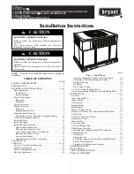
A09032
Fig. 1 -- Unit 577D----A
Checking Cooling and Heating Control Operation
28
. . . . . .
Checking and Adjusting Refrigerant Charge
28
. . . . . . . . . . .
Refrigerant Charge
29
. . . . . . . . . . . . . . . . . . . . . . . . . . . . . .
No Charge
29
. . . . . . . . . . . . . . . . . . . . . . . . . . . . . . . . . . . . .
Low Charge Cooling
29
. . . . . . . . . . . . . . . . . . . . . . . . . . . . .
To Use Cooling Charging Charts
29
. . . . . . . . . . . . . . . . . . . .
Non--Communicating Emergency Cooling/Heating Mode
29
. .
MAINTENANCE
31--34
. . . . . . . . . . . . . . . . . . . . . . . . . . . . . . . .
Air Filter
31
. . . . . . . . . . . . . . . . . . . . . . . . . . . . . . . . . . . . . . . .
Indoor Fan and Motor
31
. . . . . . . . . . . . . . . . . . . . . . . . . . . . . .
Inducer Blower
31
. . . . . . . . . . . . . . . . . . . . . . . . . . . . . . . . . . .
Limit Switch
31
. . . . . . . . . . . . . . . . . . . . . . . . . . . . . . . . . . . . .
Burner Ignition
31
. . . . . . . . . . . . . . . . . . . . . . . . . . . . . . . . . . .
Main Burners
31
. . . . . . . . . . . . . . . . . . . . . . . . . . . . . . . . . . . .
Inducer Pressure Switch
32
. . . . . . . . . . . . . . . . . . . . . . . . . . . .
Outdoor Coil, Indoor Coil, and Condensate Drain Pan
32
. . . . .
Outdoor Fan
32
. . . . . . . . . . . . . . . . . . . . . . . . . . . . . . . . . . . . .
Electrical Controls and Wiring
32
. . . . . . . . . . . . . . . . . . . . . . .
Refrigerant Circuit
33
. . . . . . . . . . . . . . . . . . . . . . . . . . . . . . . . .
Indoor Airflow
33
. . . . . . . . . . . . . . . . . . . . . . . . . . . . . . . . . . .
Pressure Switches
33
. . . . . . . . . . . . . . . . . . . . . . . . . . . . . . . . .
Loss--of--Charge Switch
33
. . . . . . . . . . . . . . . . . . . . . . . . . . . .
High--Pressure Switches
33
. . . . . . . . . . . . . . . . . . . . . . . . . . . .
Copeland Scroll Compressor (Puron
®
Refrigerant)
33
. . . . . . . .
Refrigerant System
33
. . . . . . . . . . . . . . . . . . . . . . . . . . . . . . . .
Refrigerant
33
. . . . . . . . . . . . . . . . . . . . . . . . . . . . . . . . . . . .
Compressor Oil
33
. . . . . . . . . . . . . . . . . . . . . . . . . . . . . . . . .
Servicing Systems on Roofs with Synthetic Materials
33
. . . .
Liquid--Line Filter Drier
34
. . . . . . . . . . . . . . . . . . . . . . . . . .
Puron (R--410A) Refrigerant Charging
34
. . . . . . . . . . . . . . .
TROUBLESHOOTING
34
. . . . . . . . . . . . . . . . . . . . . . . . . . . . . .
FINAL CHECKS
35
. . . . . . . . . . . . . . . . . . . . . . . . . . . . . . . . . . .
CARE AND MAINTENANCE
35
. . . . . . . . . . . . . . . . . . . . . . . .
START--UP CHECKLIST
39
. . . . . . . . . . . . . . . . . . . . . . . . . . . .


