background image

912SE: Product Data

Manufacturer reserves the right to change, at any time, specifications and designs without notice and without obligations.

7

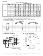
NOTE: 

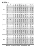
1. A filter is required for each return-air inlet. Airflow performance included 3/4-in. (19 mm) washable filter media such as contained in a factory - authorized accessory filter rack. See 

accessory list. To determine airflow performance without this filter, assume an additional 0.1 in. w.c. available external static pressure.

2. Adjust the blower airflow settings as necessary for the proper air temperature rise for each installation.

3. Airflows over 1800 CFM require bottom return, two-side return, or bottom and side return. A minimum filter size of 20” x 25” (508 x 635 mm) is required.

4. For upflow applications, air entering from one side into both the side of the furnace and a return air base counts as a side and bottom return

5. The -- entry indicates unstable operating conditions

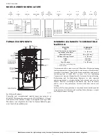
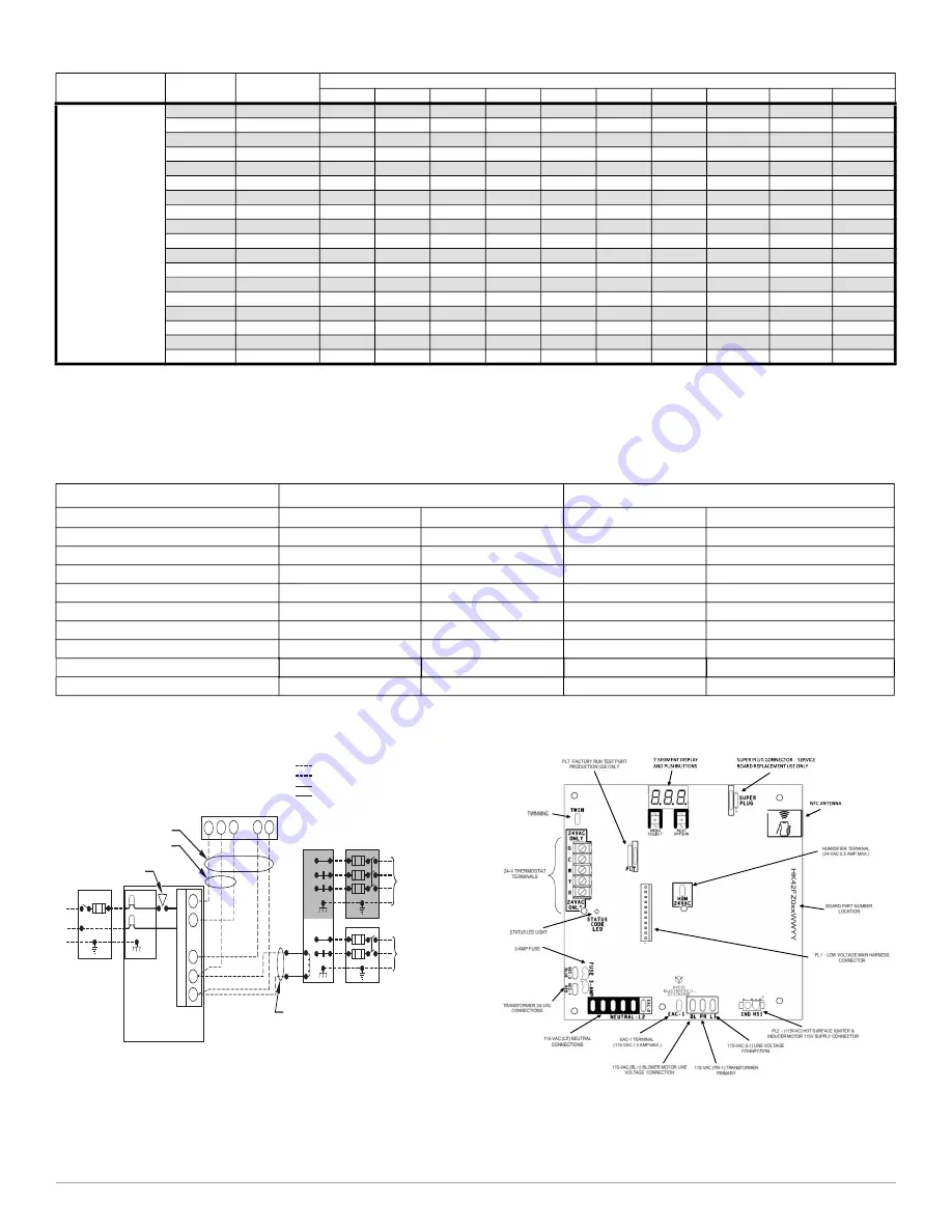
TYPICAL WIRING SCHEMATIC

A190079

FURNACE CONTROL BOARD

A210192

60120M24

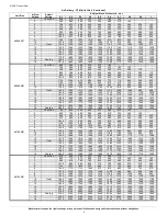
1

Cont. Fan

770

665

545

445

355

275

185

-

-

-

2

830

725

615

515

425

345

265

180

130

-

3

915

815

725

615

525

445

370

295

220

165

4

990

895

810

710

620

540

465

395

325

255

5

1085

1000

915

835

740

655

580

510

445

380

6

1170

1095

1010

935

855

765

690

620

555

490

7

1235

1160

1080

1005

935

850

770

700

635

570

8

1330

1260

1190

1115

1050

980

900

820

755

695

9

1405

1335

1270

1200

1135

1070

1000

920

850

790

10

1490

1425

1365

1295

1235

1170

1110

1040

965

900

11

1585

1525

1470

1405

1340

1285

1230

1170

1105

1030

12

1665

1605

1550

1495

1435

1375

1320

1270

1210

1145

13

1750

1700

1645

1595

1535

1480

1425

1375

1320

1270

14

1835

1785

1740

1685

1630

1575

1525

1475

1430

1385

15

Heat

1880

1830

1780

1730

1680

1625

1575

1530

1480

1435

16

1920

1875

1825

1775

1730

1675

1625

1580

1535

1490

17

1995

1945

1900

1855

1810

1760

1715

1670

1625

1585

18

Cooling

2115

2065

2020

1975

1930

1875

1815

1750

1690

1630

Air Delivery - CFM (with filter) (Continued)

Unit Size

Airflow 

Setting

Default 

Setting

External Static Pressure (in. w.c.)

0.1

0.2

0.3

0.4

0.5

0.6

0.7

0.8

0.9

1

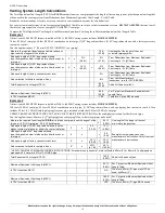
Airflow Settings

Default Airflow Settings

*

*. Setting #1 is the default setting for Constant Fan

Designated Airflow Settings

Unit Size

Heating 

Cooling

Heating 

Const. Fan

36040M14

8

18

(5-8)

(1-4)

36040M17

9

18

(4-9)

(1-1)

36060M14

12

18

(6-14)

(1-6)

42060M17

9

18

(7-14)

(1-8)

48080M17

11

17

(8-14)

(1-8)

60080M21

11

18

(7-14)

(1-8)

60100M21

13

18

(7-16)

(1-7)

66100M21

10

16

(7-12)

(1-8)

60120M24

15

18

(12-16)

(1-1)

115-V FIELD-

SUPPLIED

DISCONNECT

AUXILIARY
J-BOX

24-V

TERMINAL

BLOCK

THREE-WIRE

HEATING-ONLY

FIVE WIRE

NOTE 1

NOTE 2

FIELD-SUPPLIED
DISCONNECT

CONDENSING
UNIT

TWO
WIRE

FURNACE

C
O
N
T
R
O

L

R

G

COM

W

C

R

G

Y

GND

GND

FIELD 24-V WIRING
FIELD 115-, 208/230-, 460-V WIRING
FACTORY 24-V WIRING
FACTORY 115-V WIRING

208/230- OR
460-V
THREE
PHASE

208/230-V
SINGLE
PHASE

BLOWER DOOR SWITCH

WHT

BLK

WHT

BLK

NOTES:

Connect Y-terminal in furnace as shown for proper blower operation.
Some thermostats require a "C" terminal connection as shown.
If any of the original wire, as supplied, must be replaced, use
same type or equivalent wire.

W

   Y

GND

THERMOSTAT
TERMINALS

1.
2.
3.

Summary of Contents for 912SE

Page 1: ...rimary heat exchanger Stainless steel condensing secondary heat exchanger INSTALLATION FLEXIBILITY 4 way multipoise design for upflow downflow or horizontal installation with unique vent elbow for 12 different venting options including optional venting through the cabinet downflow venting capability On board NFC antenna makes setup a tap away when using the Bryant service technician app Factory co...

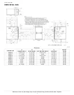
Page 2: ...2 7 1 8 181 122 55 36040M17 17 1 2 445 15 7 8 403 16 406 8 3 4 222 123 56 36060M14 14 3 16 361 12 1 2 319 12 9 16 322 7 1 8 181 128 58 42060M17 17 1 2 445 15 7 8 403 16 406 8 3 4 222 136 62 48080M17 17 1 2 445 15 7 8 403 16 406 8 3 4 222 144 65 60080M21 21 533 19 3 8 492 19 1 2 495 10 1 2 267 153 69 60100M21 21 533 19 3 8 492 19 1 2 495 10 1 2 267 160 73 66100M21 21 533 19 3 8 492 19 1 2 495 10 1 ...

Page 3: ...esulting failure damage or repairs may impact warranty coverage 1 Heat Exchanger 9 2 Tier NOx 8 3 AFUE NOx 7 4 Heating Stages M 5 Major Series B 6 7 Cooling Capacity CFM 42 8 10 Heat Input 060 11 Motor Type C 12 13 Width 17 14 Voltage 1 phase A 15 Un used 16 Minor Series A A B C 14 14 2 17 17 5 21 21 0 24 24 5 C Constant Airflow Variable Speed VCA ECM V Variable Speed VCT PWM M Multi 18 Speed Cons...

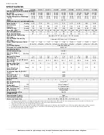
Page 4: ...ency media filter Heating 730 760 1090 935 1320 1390 1620 1600 1830 Cooling 195 1090 140 1100 320 1285 200 1340 270 1790 275 1890 295 1870 295 2220 355 1930 Direct Drive Motor HP 1 2 1 2 1 2 1 2 3 4 3 4 3 4 1 3 4 Motor Full Load Amps 6 7 6 7 6 7 6 7 8 8 8 8 8 8 11 7 8 8 Heating Blower Control Htg OFF Delay Adjustable 90 120 factory set 150 180 seconds Cooling Blower Control Clg OFF Delay Adjustabl...

Page 5: ...10 15 1060 1025 995 965 930 895 865 835 800 765 16 1110 1080 1050 1020 985 955 925 895 865 835 17 1165 1135 1105 1080 1045 1020 990 960 930 900 18 Cooling 1225 1195 1165 1135 1100 1060 1020 985 945 910 36060M14 1 Cont Fan 585 515 445 380 320 260 195 145 2 630 570 510 440 380 330 270 205 160 3 695 635 580 520 460 405 355 300 240 180 4 735 685 630 575 510 460 410 360 310 250 5 780 725 675 620 565 51...

Page 6: ...95 18 Cooling 2050 2010 1970 1930 1890 1845 1795 1745 1690 1635 60100M21 1 Cont Fan 740 640 545 455 375 295 215 140 2 830 740 650 565 480 410 335 260 190 3 905 825 740 655 575 505 440 375 300 235 4 975 900 820 740 665 585 525 465 400 335 5 1045 975 900 820 750 675 605 550 490 430 6 1130 1065 995 925 850 780 715 650 595 540 7 1210 1145 1080 1015 945 880 815 750 690 640 8 1285 1225 1165 1105 1040 97...

Page 7: ...0 965 900 11 1585 1525 1470 1405 1340 1285 1230 1170 1105 1030 12 1665 1605 1550 1495 1435 1375 1320 1270 1210 1145 13 1750 1700 1645 1595 1535 1480 1425 1375 1320 1270 14 1835 1785 1740 1685 1630 1575 1525 1475 1430 1385 15 Heat 1880 1830 1780 1730 1680 1625 1575 1530 1480 1435 16 1920 1875 1825 1775 1730 1675 1625 1580 1535 1490 17 1995 1945 1900 1855 1810 1760 1715 1670 1625 1585 18 Cooling 211...

Page 8: ... 20 45 35 25 10 10 10 35 25 10 45 30 40 10 5 20 25 20 10 20 30 25 15 10 5 10 25 15 10 30 20 Winter Design Temp C Unit Size 40 000 BTUH Not all model families have this size 60 000 BTUH Uninsulated 3 8 in Insulation 1 2 in Insulation Uninsulated 3 8 in Insulation 1 2 in Insulation Pipe Dia mm 38 51 64 38 51 64 38 51 64 38 51 64 76 38 51 64 76 38 51 64 76 7 6 1 6 1 6 1 6 1 15 2 13 7 6 1 18 3 15 2 6 ...

Page 9: ...requiring 4 in 102 mm diameter pipe Unit Size 40 000 1 60 000 2 80 000 100 000 3 120 000 Altitude feet Pipe Dia in 1 2 2 1 2 2 3 1 2 2 3 4 2 2 3 4 2 3 4 0 2000 20 85 185 20 100 175 200 15 55 130 175 200 20 80 175 200 10 75 185 2001 3000 15 80 175 95 165 185 10 49 125 165 185 15 75 165 185 70 175 3001 4000 70 160 16 90 155 175 115 155 175 155 175 5 65 165 4001 4500 10 155 15 85 150 170 44 110 150 1...

Page 10: ...ong radius elbows use the highest number of elbows for either the vent or inlet pipe 3 x 3 ft 0 9 M 9 ft 2 7 M From Deductions from Maximum Equivalent Vent Length Ft M Table Add equiv length of 2 45º long radius elbows use the highest number of elbows for either the vent or inlet pipe 2 x 1 5 ft 0 5 M 3 ft 0 9 M From Deductions from Maximum Equivalent Vent Length Ft M Table Add equiv length of fac...

Page 11: ...ntric Vent Kit A93086 A concentric vent kit allows vent and combustion air pipes to terminate through a single exit in a roof or side wall One pipe runs inside the other allowing venting through the inner pipe and combustion air to be drawn in through the outer pipe 60 80 27 C 16 C SUPPLY AIR FIELD SUPPLIED 2 IN 51 mm DIA PVC PIPE FIELD SUPPLIED 2 IN 51 mm DIA MITERED RADIUS PVC 90 ELBOW 12 300 mm...

Page 12: ... X X KGARP0301B14 Return Air Base Upflow Applications 14 wide X X KGARP0301B17 Return Air Base Upflow Applications 17 1 2 wide X X KGADC0101BVC Vent Kit Through the Cabinet X X X X KGAVT0701CVT Vent Terminal Concentric 2 51 mm See Venting Tables KGAVT0801CVT Vent Terminal Concentric 3 76 mm KGAVT0101BRA Vent Terminal Bracket 2 51 mm KGAVT0201BRA Vent Terminal Bracket 3 76 mm KGAAC0101RVC Vent Kit ...

Page 13: ...C0101RVC Polypropylene Inlet Air Pipe Coupling X X X X X KGAHT0101CFP Freeze Protect Kit Condensate Drain Line Tape X X X X X KGAHT0201CFP Freeze Protect Kit Condensate Trap with Heat Pad X X X X X KGAAD0110PVC CPVC to PVC Drain Adapters 1 2 CPVC to 3 4 PVC X X X X X KGACK0101HCK Horizontal Trap Grommet Direct Vent All 2 Pipe Horizontal KGAET0201ETK External Trap Kit X X X X X KGASB0201ALL Downflo...

Page 14: ... 508 mm MERV11 FILXXCAR0120 X Cartridge Media Filter 24 610 mm MERV 8 FILXXCAR0024 X Cartridge Media Filter 24 610 mm MERV11 FILXXCAR0124 X EZ Flex Cabinet Side or Bottom 16 EZXCAB 0016 X X EZ Flex Cabinet Side or Bottom 20 EZXCAB 0020 X X EZ Flex Replacement Filters 16 MERV 10 EXPXXFIL0016 X X EZ Flex Replacement Filters 16 MERV 13 EXPXXFIL0316 X X EZ Flex Replacement Filters 20 MERV 10 EXPXXFIL0...

Reviews: