15
A06485
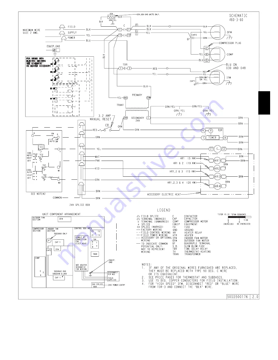
Fig. 15 -- Wiring Diagram 460--3--60
704A
Page 1: ...iston 18 TROUBLESHOOTING 18 START UP CHECKLIST 18 C99062 Fig 1 Unit 704A SAFETY CONSIDERATIONS Installation and servicing of this equipment can be hazardous due to mechanical and electrical components...
Page 2: ...e that the fan discharge does not recirculate to the outdoor coil Do not locate the unit in either a corner or under an overhead obstruction The minimum clearance under a partial overhang such as a no...
Page 3: ...UNIT 2 00 50 8 SIDE OPPOSITE DUCTS 14 00 355 6 BOTTOM OF UNIT 0 50 12 7 NEC REQUIRED CLEARANCES INCHES mm BETWEEN UNITS POWER ENTRY SIDE 42 00 1066 8 UNIT AND UNGROUNDED SURFACES POWER ENTRY SIDE 36...
Page 4: ...m BETWEEN UNITS POWER ENTRY SIDE 42 00 1066 8 UNIT AND UNGROUNDED SURFACES POWER ENTRY SIDE 36 00 914 0 UNIT AND BLOCK OR CONCRETE WALLS AND OTHER GROUNDED SURFACES POWER ENTRY SIDE 42 00 1066 8 Refer...
Page 5: ...port CTyp G E F G D E A05308 UNIT SIZE ODS CATALOG NUMBER A IN MM B IN MM C IN MM D IN MM E IN MM F IN MM G IN MM 704A024 030 CPRFCURB006A00 8 203 11 279 16 1 2 419 28 3 4 730 30 3 8 771 44 5 16 1126...
Page 6: ...to follow this warning could result in personal injury or death Never stand beneath rigged units or lift over people WARNING INSTALLATION The lifting rigging bracket is engineered and designed to be i...
Page 7: ...Be sure to check the drain tube for leaks Prime trap at the beginning of the cooling season start up 1 25mm MIN 2 50mm MIN TRAP OUTLET C99013 Fig 8 Condensate Trap Step 7 Install Duct Connections Thed...
Page 8: ...sion of vibration The transition may be screwed or bolted to duct flanges Use suitable gaskets to ensure weather tight and airtight seal 4 All units must have field supplied filters or accessory filte...
Page 9: ...the line side of the contactor 4 Connect field L1 to black wire on connection 11 of the compressor contactor 5 Connect field wire L2 toyellow wireon connection13 ofthe compressor contactor 6 Connect...
Page 10: ...nal box if refrigerant leak is suspected around compressor terminals 3 Never attempt to repair soldered connection while refrigerant system is under pressure 4 Do not use torch to remove any component...
Page 11: ...efrigerant charge is not required unless the unit is suspected of not having the proper R 22 charge A superheat charging chart is attached to the outside of the service access panel The chart includes...
Page 12: ...604 1538 1457 1362 1271 High Watts 798 772 738 700 CFM 1720 1648 1540 1414 048 Low Watts 627 617 607 584 567 548 528 503 CFM 1550 1530 1493 1461 1414 1361 1320 1250 Med Watts 771 755 734 711 690 665 6...
Page 13: ...13 A05112 Fig 13 Wiring Diagram 208 230 1 60 704A...
Page 14: ...14 A06307 Fig 14 Wiring Diagram 208 230 3 60 704A...
Page 15: ...15 A06485 Fig 15 Wiring Diagram 460 3 60 704A...
Page 16: ...nit wire Y and time delay relay TDR through unit wire G across the 24 v secondary of transformer TRAN The normally open contacts of energized contactor C close and complete the circuit through compres...
Page 17: ...se from the blower wheel and motor annually ELECTRICAL SHOCK HAZARD Failure to follow this warning could result in personal injury or death Disconnect and tag electrical powerto theunit beforecleaning...
Page 18: ...ssemble the connection properly and securely After inspecting the electrical controls and wiring replace all the panels Start the unit and observe at least one complete cooling cycle to ensure proper...
Page 19: ...e cause Insufficient line voltage Determine cause and correct Blocked outdoor coil Determine cause and correct Defective run start capacitor overload or start relay Determine cause and replace Faulty...
Page 20: ...TNESS III START UP ELECTRICAL SUPPLY VOLTAGE __________________________________ COMPRESSOR AMPS_________________________________ INDOOR EVAPORATOR FAN AMPS___________ TEMPERATURES OUTDOOR CONDENSER AI...