


13
WIRING DIAGRAMS (CONTINUED)
5
2
6
6
(
5
3
0
2
&
1
$
)
&
'
1
&
85
96
:&
/,1
1,1
&7
%/8(
%/$&.
8
9
:
&1
0$,1%2$5'
&1
7
7
3
5('
',6&+$5*(6(1625
&1
&1
*1'
&20
5<
21
1287
&1
1
&
1
&
a a
1
&
1
&
,30%2$5'
5('
5($&725
%/8(
%/8(
%/8(
K
C
A
L
B
D
E
R
L-OUT
<*
&1
1
&
1
&
&1
2
1
&
&1
5('
%/8(
&1 &1
+($7(5
+($7
&1 &1
:$<
:$<
+($7(5
&1 &1
+($7
287'225$0%,(17
7(03(5$785(6(1625
&21'(16(5
7(03(5$785(6(1625
Y/G
D
E
R
/ / 6 / /
72,1'22581,7 32:(56833/<
K
C
A
L
B
/ /
CN10
S
YELLOW
Y/G
/ /
S
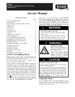
Fig. 10 – Wiring Diagram for 24K 208/230V
Table 11—Outdoor Unit Control Board
CODE
INPUT or OUTPUT VALUE
L_IN
Power Voltage
:
AC 230V
CN11
Power Voltage
:
AC 230V
CN16
Relative to the N terminal voltage
:
DC24V
CN15
Maximum voltage
:
DC 5V
CN6
Maximum output voltage
:
AC230V
CN4
Indoor fan interface, Maximum voltage
:
DC310V
CN5
Stepper motor interface, Maximum voltage between the lines
:
DC12V
P_1
Ground
CN8
Room temperature sensor interface, maximum voltage
:
DC 5V
CN9
Pipe temperature sensor interface, maximum voltage
:
DC 5V
CN10A
Display interface, maximum voltage between the lines DC5V
CN14
Stepper motor interface (optional), maximum voltage between the lines
:
DC12V


