


DO NOT INSTALL A BAROMETRIC DRAFT
CONTROL IN A ROOM SEPARATE FROM THE
BOILER.
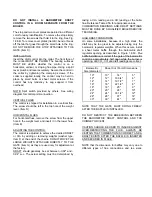
The stop and two cover plates are painted in a different
color for easy identification. To remove the stop simply
remove the two screws that hold it to the ring. See Fig.
1.8.6B. To remove cover plates (Item B), bend or break
off the tab that goes through the small hole in the ring.
DO NOT REMOVE THE STOP ATTACHED TO THE
GATE (Item C).
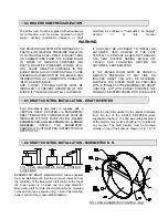
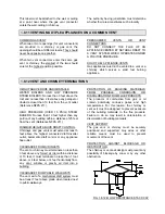
INSTALLATION
Insert the draft control into the collar. The front face of
the control MUST BE PLUMB. The bearing surfaces
MUST BE LEVEL whether the control is on a
horizontal, vertical, or sloping flue pipe. Using a spirit
level, plumb and level accurately. Secure the control in
the collar by tightening the clamping screws. If the
collar is supplied locally, the control may be held in
place by small bolts or sheet metal screws. If the
control has any tendency to sag support it from
overhead.
NOTE: Spill switch provided by others. See wiring
diagram for control point connection.
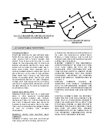
VERTICAL FLUES
The control is shipped for installation in a vertical flue.
The screw should be left in the top hole of the weight
lever. (Item D)
HORIZONTAL FLUES
For horizontal flues, remove the screw from the upper
hole in the weight lever and insert it in the lower hole.
(Item E)
ADJUSTING THE CONTROL
The control is adjusted to achieve the desired DRAFT
or CO
2
by adding or removing weights (washer type,
Item F) at the end of the chains. DO NOT MOVE THE
LARGE WEIGHTS ATTACHED DIRECTLY TO THE
GATE (Item G) as they are used only for adjustment at
the factory.
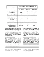
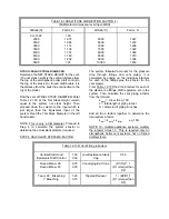
DRAFT should generally be set between -0.02" and -
0.04" w.c. The actual setting must be determined by
taking a CO
2
reading and a CO reading at the boiler
flue. Reference Table 2.5A for appropriate values.
COMBUSTION READINGS AND DRAFT SETTINGS
MUST BE DONE BY A QUALIFIED BOILER SERVICE
TECHNICIAN.
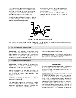
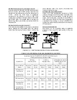
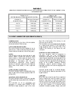
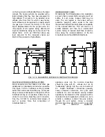
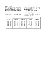
HIGH DRAFT CONDITIONS
On some installations, because of a high stack, the
draft may be too great to be adjusted using only the
barometric regulator weights. When this occurs, install
a sheet metal baffle through the barometric draft
regulator opening as described in Figure 1.8.6C. The
baffle installation is correct if the gate of the barometric
control is approximately half open while the burner is
operating, and CO
2
, CO and draft readings are correct.
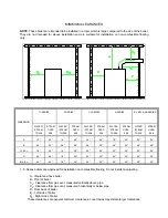
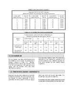
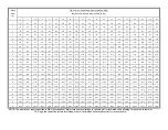
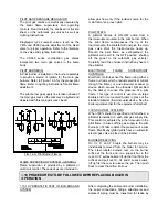
Barometric
Size (diameter)
Sheet Cut / Form Dimensions
10"
12"
14"
16"
18"
20"
24"
28"
30"
10"
12"
14"
16"
18"
20"
24"
28"
30"
14"
16 3/4"
19 1/2"
22 1/2"
25"
28"
33 1/2"
37"
44"
5"
6"
7"
8"
9"
10"
12"
14"
16"
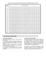
NOTE THAT THE GATE MUST SWING FREELY
AFTER THE BAFFLE IS INSTALLED.
DO NOT RESTRICT THE BREECHING BETWEEN
THE BAROMETRIC DRAFT CONTROL AND THE
CHIMNEY OR VENT.
CAUTION SHOULD BE USED TO INSURE AGAINST
OVER-RESTRICTING THE FLUE. ALWAYS BE
CERTAIN THAT COMBUSTION IS CORRECT AND A
DRAFT EXISTS AFTER THE BAFFLE IS INSERTED
AND SECURED IN PLACE.
NOTE that the dimension for baffles may vary due to
different types of flue connections and tee sizes.
Summary of Contents for AB Series
Page 22: ......


