background image


1 3 


STEP 3 – Install & Configure BioKey Software


Insert the CDROM and run the BioKey.exe file, or wait for the auto starter to 
launch the application for you. 
Install the software to a location on your computer that you wish to have it 

operate and run from. Please note the BioLock software requires no 
installation or dependencies therefore the software installer is only just 
copying files to a location you specify. Copies of the two files required to run 

BioKey are located on the CDROM under the \Source Files directory. 
These files are: 


BioKey.exe ( Main Executable) 


BioLockAPI.dll ( Communications and Matching DLL) 

 
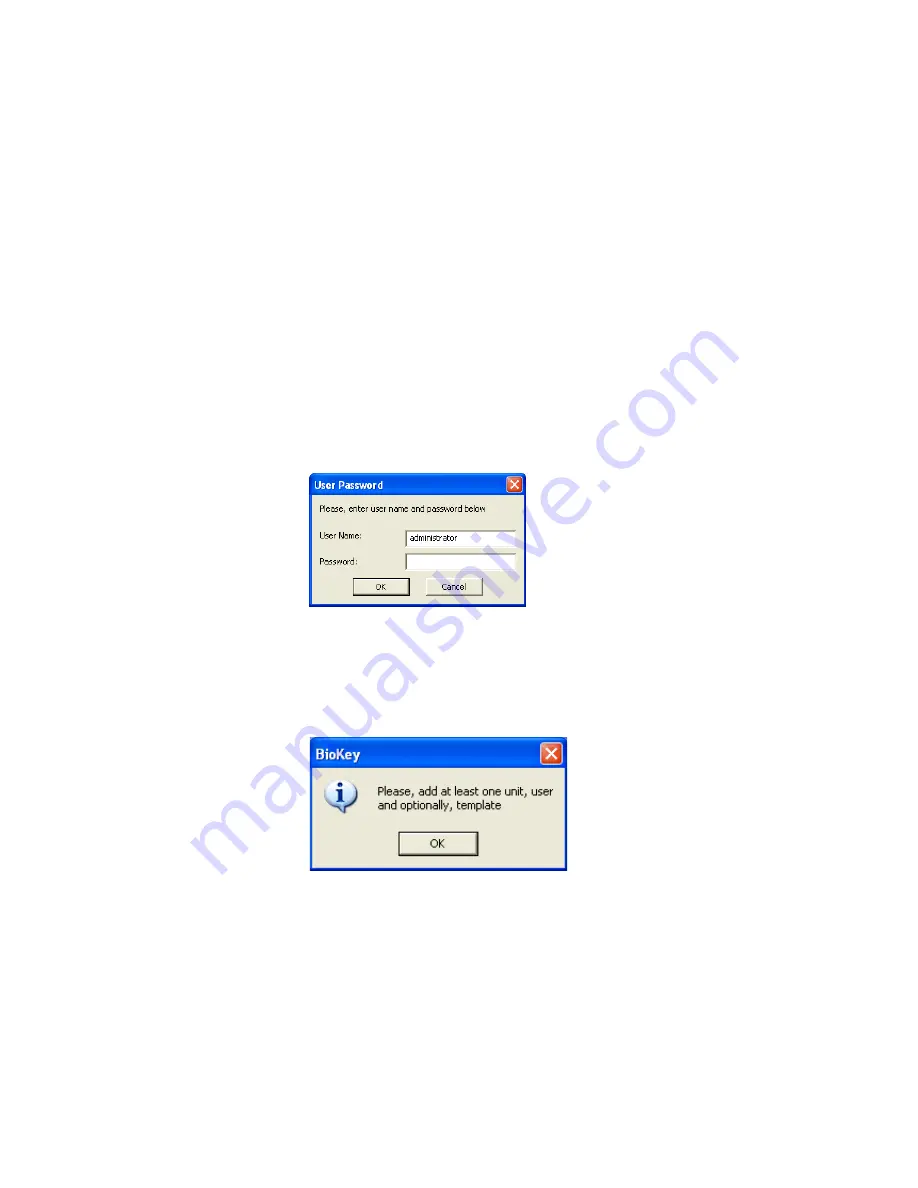
Once installed run the Program from the Start, Programs BioKey Directory or 
from the desktop where a shortcut has also been installed, the following 

program window will appear. 
 
Login password by default on startup is left blank so just press Enter 


BioKey is designed to assist you in first starting and configuring the software 

via a Wizard which will first appear after installation. You must first configure 
the Unit in the software and add a user before you can enrol a template.  
 

Follow the prompts to add a unit and user. 


Summary of Contents for BioLock

Page 1: ... io oL Lo oc ck k U Us se er rs s G Gu ui id de e V Ve er rs si io on n 1 1 0 0 Bio Recognition Systems Pty Ltd Unit 11 Building F 16 Mars Rd Lane Cove NSW Australia 2066 Ph 61 2 9882 8600 Fax 61 2 9427 2503 ...

Page 2: ... Trademarks BioLock BioKey are all registered trademarks of Bio Recognition Systems Pty Ltd Microsoft Windows NT and MS DOS are registered trademarks of Microsoft Corporation Copyright Copyright 2005 Bio Recognition Systems Pty Ltd All rights reserved Reproduction or transmittal of this publication or portions of the publication is prohibited without the express prior and written consent of the pu...

Page 3: ... Standards Compliance 7 INTRODUCTION 8 HARDWARE INSTALLATION 9 INSTALLING BIOLOCK 9 HARDWARE PROGRAMMING 17 PROGRAMMING BIOLOCK 17 ENTERING ADMIN MODE 17 CONNECTING THE SECURE RELAY BOARD 17 PROGRAMMING THE BIOLOCK RELAY ON TIME 17 TESTING THE RELAY ON TIME DURATION ERROR BOOKMARK NOT DEFINED ADDING USERS 18 DELETING USERS 18 DELETING ALL USERS 18 VERIFYING USERS 18 FACTORY DEFAULT 18 USING BIOLOC...

Page 4: ......

Page 5: ...earch Development and BioMetrics Manufacturer based in Sydney NSW Australia Since early 2000 we have been developing and supporting our range of BioMetric Security and Time Management software and hardware solutions This latest product BioLock is a fully embedded finger print device that incorporates all of the features of the more expensive competitive units along with many additional features Co...

Page 6: ...r by the customer All warranties require that the unit be return back to Bio Recognition Systems Pty Ltd for servicing or repaired through an authorised distributor of Bio Recognition Systems Pty Ltd Finger Sensors or parts that can suffer from wear tear are not covered under this warranty Finger Sensors Power supplies and batteries supplied with Bio Recognition Systems Pty Ltd products are warran...

Page 7: ...l Biometrics Standards Compliance The product has been tested and has compliance to the following standards BioAPI Compliant ANSI INCITS 358 2002 CBEFF Common Biometric Exchange File Format Compliant NISTIR 6529 2001 ...

Page 8: ...loyees Incorporating standard 10BaseT communications technology BioLock provides users the ability to run long distances including over the internet removing distance restrictions BioLock can be installed outdoors as it is weather rated to IP65 which means it can handle water jets of low to medium pressure directly without the concerns of damage or ingress into electronic circuitry Being weather r...

Page 9: ...he supplier who can replace missing components Device LED Indicators Power On Green Led The Green Led indicates power to the device Identify Success Enrolment Yellow Led The Yellow Led indicates a successful scan has taken place also it is used for Enrolment assistance Identity Fail Red Led The Red Led indicates a failed scan has taken place and Is also used for assistance with enrolments Power Re...

Page 10: ... Terminate all wires used and unused in the screw strips provided to eliminate shorting or failures The 8 Pin White connector on the cable must be passed through the 7mm hole via the rear or back of the metal backplate closest to the wall and in doing the grommet placed on the cable must be tightly inserted into the 7mm hole Leave ample cable hanging out of the hole whilst mounting so that you can...

Page 11: ...weather proofing Do not remove this lubricant as it is important to the performance of the seal The front housing is designed to come together with the bracket 5 degrees slightly to the left off centre and engage 4 key slots by the heads of the screws protruding from the front housing Once the screws are engaged through the holes the unit may be rotated 5 degrees to the right to the position where...

Page 12: ...our PC correctly Open up Internet Explorer and type in the address bar http 192 168 0 210 The BioLock Home Page window should appear Select Network to Change the IP and Address Settings of the BioLock Select Sensor Diagnostics to View Images after you have installed software and hardware Select Led Buzzer to Manually Turn on Led s and Sound Buzzer Select Tamper to Ensure that the Tamper Switch is ...

Page 13: ...located on the CDROM under the Source Files directory These files are BioKey exe Main Executable BioLockAPI dll Communications and Matching DLL Once installed run the Program from the Start Programs BioKey Directory or from the desktop where a shortcut has also been installed the following program window will appear Login password by default on startup is left blank so just press Enter BioKey is d...

Page 14: ...he wizard will now prompt you to enter the unit details Enter a Unit Name ID and the correct IP address you have assigned You may now enrol a user and template Now you are required to enrol a user template ...

Page 15: ...15 Once a Unit and User are Configured the Main Form will show ...

Page 16: ...cure I O Configuration and installation of Secure I O PCB Once you select OK The system is now ready to operate Any person enrolled who touches the BioLock device as long as they have rights then the Secure Relay Board will operate ...

Page 17: ...the unit Red and Green Leds at the top will flash indicating no users are enrolled Place any Administrators finger on the unit and leave it on the sensor for 5 seconds Quickly remove finger from sensor You are now in Administrator Mode and BioLock is ready to have additional user templates enrolled Connecting the Secure Relay Board The Secure Relay Boards become known to the BioLock units automati...

Page 18: ...inger If the finger was placed in the same position each time within parameters the GREEN led will come on and the RED will remain off indicating ENROL OK Deleting Users Can only be achieved via the BioKey software Deleting All Users Can only be done from BioKey Software Verifying Users Verifying is a test for a recently enrolled user The user only needs to place their finger on the sensor firmly ...

Page 19: ...rprint by contacting the sensor surface with the finger placed flat on the sensor as opposed to presenting only the tip of the finger The fingertip alone contains insufficient image data for a high quality fingerprint The ridges in this area are mostly parallel lines with few distinct minutiae from which to construct an identification template It is unlikely that the image management algorithm wil...

Page 20: ...FRR The FRR is the measurement of the probability that a biometric system will fail to identify an individual who is properly enrolled False Acceptance In biometric systems in general false acceptance errors are the less frequent of the two problems In the case of the BioLock sensor false acceptance is extremely rare and so far always the result of a bad enrollment False Rejection For various reas...

Page 21: ...at the fingerprint core is kept as centered as possible AT all times the finger must be flat as possible this ensures that the RF signal is correctly directed into the finger to provide a good finger image A good firm press MUST be provided Outer sensor array silver finish approx 3 mm wide Internal Sensor Array Fingerprint Core under nail cuticle Finger ...

Page 22: ......

Page 23: ...23 Appendix A G GL LO OS SS SA AR RY Y For future use ...

Page 24: ......

Page 25: ...below address fax or email Bio Recognition Systems Pty Ltd Unit 11 Building F 16 Mars Rd Lane Cove NSW AUSTRALIA 2066 Phone 612 9882 8600 Fax 612 9427 2503 Email jonreid brsgrp com BioLock Getting Started Version 1 0 0 Company Address Phone Fax Excellent Good Fair Poor Completeness Readability Format Accuracy Examples Usefulness In what ways could this manual be improved ...

Reviews: