Cooling System
Operation
194
Operation
All models use a two-stage cooling system
design. The cooling system is dependent on water
pump pressure and controlled by thermostat and
pressure valve operation.
Cylinder Block / Cylinder Head
Cooling
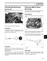
The flow of water through the cylinder block and
cylinder heads is controlled by two thermostats
and one external pressure valve. The pressure
valve is connected by hoses to the top of each cyl-
inder head.
The thermostats and pressure valve control the
flow of water entering the vertical water passages
of the cylinder heads.
At low speed
, the pressure valve is against the
seat and the thermostats are closed. Warm water
from the cylinder block gradually migrates to the
thermostat pocket at the top of each cylinder
head.
The thermostat opens when the water tempera-
ture reaches approximately 143°F (62°C).
When the thermostat opens, water flows down
through the cylinder head to a passage in the cyl-
inder block. Water flows through the block to the
exhaust housing and then out of the outboard.
At higher speeds
, water pressure opens the
pressure relief valve at approximately 1200 RPM.
Water flows through the valve and bypasses the
thermostats. Hoses route the water flow from the
pressure valve to the vertical water passages
below the thermostats. All water flows through the
cylinder heads to the outlet passages of the block
and then exits through the adapter housing.
This pressure controlled water outlet circuit pro-
vides a “high flow” discharge of water during high
speed operation.
This cooling system configuration provides “bal-
anced cooling” at higher RPM by using one pres-
sure valve to control the discharge of water
through both cylinder heads.
Additional Cooling
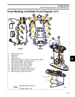
Two external water supply hoses direct water flow
into the exhaust (plenum) area of the cylinder
block. The water reduces exhaust runner tem-
peratures and circulates through the cylinder
block.
The base gasket limits water flow to the base of
the block and diverts water flow to the rear port
and rear starboard fittings of the adapter housing.
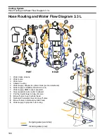
On 3.3 L models, a third external water hose
directs water flow from the exhaust housing of the
cylinder block to an exhaust passage at the
NOTICE
Restricted or inadequate water flow through
the outboard reduces cooling system perfor-
mance and may lead to severe powerhead
damage.
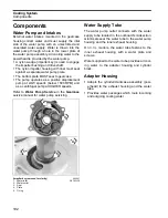
1.
Thermostats
2.
Pressure valve assembly
004269
1
1
2
Summary of Contents for EVINRUDE E-TEC BE225HGXABA
Page 163: ...Oiling System Oil Supply Diagrams 163 8 008208R Port Side View Starboard Side View ...
Page 165: ...Oiling System Oil Supply Diagrams 165 8 008432R Port Side View Starboard Side View ...
Page 167: ...Oiling System Oil Recirculation Diagrams 167 8 008207R Starboard View Port View ...
Page 251: ...Powerhead Powerhead Views 251 11 Powerhead Views Port Hose Routings 3 3 L models 007153 ...
Page 252: ...252 Powerhead Powerhead Views Starboard Hose Routings 3 3 L models 007154 ...
Page 253: ...Powerhead Powerhead Views 253 11 Port Hose Routings 3 4 L models 008503 ...
Page 254: ...254 Powerhead Powerhead Views Starboard Hose Routings 3 4 L models 008502 ...
Page 255: ...Powerhead Powerhead Views 255 11 Port 3 3 L models 008448 ...
Page 256: ...256 Powerhead Powerhead Views Starboard 3 3 L models 008449 ...
Page 257: ...Powerhead Powerhead Views 257 11 Port 3 4 L models 008441 ...
Page 258: ...258 Powerhead Powerhead Views Starboard 3 4 L models 008442 ...
Page 259: ...Powerhead Powerhead Views 259 11 Front 3 3 L models 008450 ...
Page 260: ...260 Powerhead Powerhead Views Front 3 4 L models 008439 ...
Page 261: ...Powerhead Powerhead Views 261 11 Rear 3 3 L models 007142 ...
Page 262: ...262 Powerhead Powerhead Views Rear 3 4 L models 008440 ...
Page 263: ...Powerhead Powerhead Views 263 11 Top 008438 ...
Page 264: ...264 Powerhead Powerhead Views Starboard ICON models 008504 ...
Page 269: ...Midsection Service Charts 269 12 Muffler 004117R ...
Page 320: ...S 322 ...

