background image

B.U.D.S. PROGRAMMING

vmr2006-012-100_aen

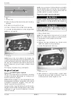
B.U.D.S. is now ready to use. Refer to

D.E.S.S.

KEY PROGRAMMING

to complete procedure.

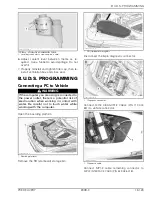
The MPI-2 includes 2 status lights to show the
connection conditions: USB and CAN.

Both lights

must be GREEN

so that MPI-2 works properly.

vdd2006-001-151_b

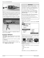
NOTE:

If an “X” is shown in the status bar, it

means that no "ECU" is communicating with the
MPI.

mmr2009-020-001

Check the following:

– MPI protocol in B.U.D.S.
– Connections between the PC computer and the

vehicle.

If

No vehicle detected...

message box is dis-

played in B.U.D.S., refer to

COMMUNICATION

TOOLS AND B.U.D.S. SOFTWARE

subsection in

the appropriate

SHOP MANUAL

.

If

Some of the information normally dis-

played...

message box is displayed in B.U.D.S.,

refer to

COMMUNICATION TOOLS AND B.U.D.S.

SOFTWARE

subsection in the appropriate

SHOP

MANUAL

.

D.E.S.S. Key Programming

The D.E.S.S. keys are color-coded to differentiate
them.

D.E.S.S.

KEY TYPE

COLOR

Normal key

YELLOW or BLACK

Learning key

GREEN

Rental key

ORANGE

Install a D.E.S.S. key, to be added or erased, on
watercraft D.E.S.S. post.

smr2009-035-005_a

1. Key to be added or erased

Briefly press start/stop button to power the ECM.

Engine must not crank.

NOTE:

Press the start/stop button every three

minutes otherwise the electrical system will shut
off.

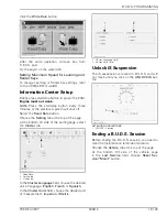
Click on

Keys

tab.

smr2005-072-001_en

Adding a Key

Click on the desired

Add Key

button on bottom

of screen according to the type of key you want
to program.

PREDELIVERY

2009-3

17 / 23

Summary of Contents for 189A

Page 1: ...Cover 12 Compliance Label 12 Vehicle Decal 12 Accessories 12 FLUIDS 12 General Guidelines 12 Fuel 12 Engine Oil 12 Engine Coolant 14 B U D S PROGRAMMING 15 Connecting a PC to Vehicle 15 B U D S Software 16 D E S S Key Programming 17 Information Center Setup 19 Unlock iS Suspension 19 Ending a B U D S Session 19 ADJUSTMENTS 20 Steering Alignment 20 FUEL SYSTEM PRESSURIZATION 21 Fuel System Pressuri...

Page 2: ...features models or equipment without incurring obligation The illustrations in this document show the typical construction of the different assemblies and may not reproduce the full detail or exact shape of the parts however they represent parts that have the same or similar function The content of this bulletin is designed as a guideline only All mechanics performing predelivery pro cedures shoul...

Page 3: ... Remove rear retaining screws from crate base sbl2009 004 001_a 1 Rear retaining screws 2 Cut front retaining strap sbl2009 004 002_a 1 Front retaining strap 3 Remove protective wrapping from vehicle NOTICE While manipulating to cut take care not to damage trim components with blade 4 Lift vehicle using the LIFTING STRAP P N 529 036 171 NOTICE Using any other lifting strap kit than the recommended...

Page 4: ...fer to RELEASING MOVING DECK subsection 2 M8 washer P N 250 200 011 2 Refer to RELEASING MOVING DECK subsection 2 Plastic cap P N 291 002 950 3 Refer to RELEASING MOVING DECK subsection 2 Battery hardware P N 250 000 282 4 Refer to BATTERY subsection 1 M6 x 45 bolt P N 207 164 560 5 Refer to BATTERY subsection 2 M6 washer P N 234 062 600 6 Refer to BATTERY subsection 2 M6 nut P N 232 561 200 7 Ref...

Page 5: ...rom hole 3 Put a knot at the end of the cable to prevent it from going into the hole sbl2009 004 007_a 1 Cable free end 2 Hole 4 Slowly unscrew rear retaining screw Do not use pneumatic or electric tools sbl2009 004 008_a 1 Rear retaining screw 5 Carefully lift rear tab upwards using a flat screwdriver sbl2009 004 009_a 1 Rear tab NOTE After lifting the rear tab the cable will slide into the hole ...

Page 6: ...ver charge or boost battery while installed in watercraft NOTICE Always charge battery before its in stallation on the vehicle NOTICE Make sure not to squeeze battery ca bles between vehicle components Battery Removal 1 Open the boarding platform ssi2009 002 002_a 1 Boarding platform 2 Remove the RH starboard storage bin NOTE The storage bin is secured using two plas tic rivets ssi2009 002 003_a 1...

Page 7: ...ry cables exactly in this specific order Connect RED positive cable first then BLACK negative ground cable 1 Install charged battery into battery holder 2 Secure battery on battery holder using the fol lowing hardware from predelivery kit M6 x 45 bolts M6 flat washers M6 nuts sbl2009 004 050_a 1 M6 x 45 bolt 2 M6 flat washer 3 M6 nut 3 Tighten bolts to 5 N m 44 lbf in 4 Position battery holder on ...

Page 8: ...g brackets 3 Install M6 x 25 screws from predelivery kit 4 Torque M6 screws to 10 N m 89 lbf in NOTE For an easier installation place small shafts into the housing cavities to lock the boarding step downwards sbl2009 004 015_a 1 Small shaft Steering Column Installation International Models 1 Cut retaining strap that holds front storage cover to vehicle NOTICE Properly hold the front storage cover ...

Page 9: ...ining collar 7 Disconnect gauge connector 8 Disconnect steering connectors from vehicle harness sbl2009 004 106_a 1 Gauge connector 2 Steering connectors 9 Remove gauge support by lifting it upwards us ing a screwdriver sbl2009 004 107_a 10 Cut retaining strap that holds steering column 11 Carefully remove steering column from foam sbl2009 004 108 12 Remove foam from vehicle 13 Remove front storag...

Page 10: ...ushings are properly inserted into steering support smr2009 037 028_a 1 Upper bushing 2 Steering column support 3 Lower bushing 18 Carefully drive steering column through steer ing column support Ensure to not hit the O T A S magnet during steering column in stallation 19 Insert steering harness through the front mod ule opening NOTE Do NOT insert gauge connector into front module opening sbl2009 ...

Page 11: ...ect gauge connector sbl2009 004 116_a 1 Gauge connector 26 Install gauge support cover 26 1 Soften the bottom portion of cover using an incandescent or halogen light 26 2 First insert the top of the cover 26 3 Press both lower sides of cover to lock tabs sbl2009 004 118 Steering Cable International Models 1 Verify if steering cable is properly installed into its support 2 Perform steering alignmen...

Page 12: ...cal 1 Install decals on vehicle according to customer country language and local legislation 2 Ensure that the new decals are installed at the same location and over the factory installed de cals Accessories 1 Install accessories if any as per their installa tion instructions included in each kit 2 Install any other equipment required by law if any FLUIDS General Guidelines All fluids except fuel ...

Page 13: ...ter the heat exchanger in the ride plate may become very hot Avoid any contact with the ride plate as burns may occur 1 Place vehicle level NOTE The watercraft is level when it is in water When on a trailer raise trailer tow pole and block in this position when bumper rail is level 2 Open seat and remove the rear ventilation box from the deck extension to gain partial access to engine compartment ...

Page 14: ...con tribute to protect the environment Cooling system must be filled with water and an tifreeze solution 50 demineralized water 50 antifreeze or use the BRP PREMIXED COOLANT P N 219 700 362 NOTE Using a blend of 40 antifreeze with 60 demineralized water will improve the cooling effi ciency when watercraft is used in particularly hot weather and or hot water condition Engine Coolant Level Verificat...

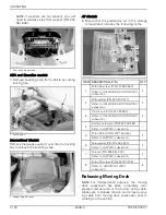
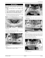
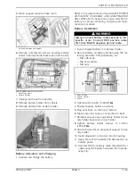
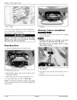
Page 15: ...to the power outlet there is a potential risk of electrocution when working in contact with water Be careful not to touch water while working with the computer Open the boarding platform ssi2009 002 002_a 1 Boarding platform Remove the RH starboard storage bin ssi2009 002 003_a 1 RH starboard storage bin Disconnect the 6 pin diagnostic connector ssi2009 002 004_a 1 Diagnostic connector Connect MPI...

Page 16: ...t stop button the ECM will stop communicating with B U D S Therefore all pending operations with B U D S will be temporarily interrupted until the start stop button is briefly pressed To avoid the interruption it is recommended to periodically briefly pressing the start stop button before the ECM stops communicating Engine must not crank Before writing data to the ECM always quickly press the star...

Page 17: ... SHOP MANUAL If Some of the information normally dis played message box is displayed in B U D S refer to COMMUNICATION TOOLS AND B U D S SOFTWARE subsection in the appropriate SHOP MANUAL D E S S Key Programming The D E S S keys are color coded to differentiate them D E S S KEY TYPE COLOR Normal key YELLOW or BLACK Learning key GREEN Rental key ORANGE Install a D E S S key to be added or erased on...

Page 18: ...ired Add Key button If programming is complete write the changes to the ECM Refer to WRITING CHANGES TO ECM in this subsection Erasing one Key Install the key to be erased to the watercraft D E S S post smr2009 035 005_a 1 Key to be erased Click on Erase Key button at bottom of B U D S screen smr2009 035 004_a 1 Click on this button After approximately 10 seconds the following message will appear ...

Page 19: ...ect the Cluster tab smr2009 036 001_a 1 Read Data 2 Setting tab 3 Cluster tab In the Cluster Language field choose the desired unit of language English French or Spanish In the Cluster Units field choose the desired unit of measurement Imperial or Metric smr2008 028 002_a 1 Cluster Language field 2 Cluster Units field Unlock iS Suspension The iS suspension is locked in B U D S and will not move un...

Page 20: ...wo bungee cords to maintain steering dur ing the procedure Position steering so that the edge of the steering column cover and edge of the gauge support are equal smr2009 037 055_a 1 Steering column cover edge 2 Gauge support edge Check jet pump nozzle position by placing a straight edge on nozzle outer end Measure the distance on each side of the straight edge It must be equalled smr2009 037 003_...

Page 21: ...aft thoroughly and polish NOTICE Clean apparent fiberglass and plastic parts with a clean cloth and soapy water or isopropyl alcohol Never use strong detergent degreasing agent paint thinner acetone etc Do not apply isopropyl alcohol directly on decals Delivery to Customer 1 Where possible give a brief demo ride and ex plain watercraft operation 2 Complete PREDELIVERY CHECK LIST follow ing all ins...

Page 22: ...m 3 9 in Stroke 63 4 mm 2 1 2 in Compression ratio 8 4 1 Cooling Closed loop system ELECTRICAL SYSTEM Ignition IDI inductive discharge ignition Starter Electric Battery 12 V 30 A h Electrolyte type Make and type NGK DCPR8E Spark plug Gap 0 75 mm 030 in PROPULSION Propulsion system Sea Doo direct drive Type Axial flow single stage Large hub with 10 vane stator Jet pump Material Aluminum Impeller St...

Page 23: ... for optimum performance Outside North America 95 RON Fuel Tank capacity 70 L 18 6 U S gal Type XPS summer grade Refer to MAINTENANCE section for more information Engine oil Capacity 3 L 2 7 U S qt oil change w filter Coolant type Ethylene glycol 50 50 antifreeze and demineralized water Coolant containing corrosion inhibitors for internal combustion aluminum engines Cooling system Capacity 5 5 L 5...

Reviews: