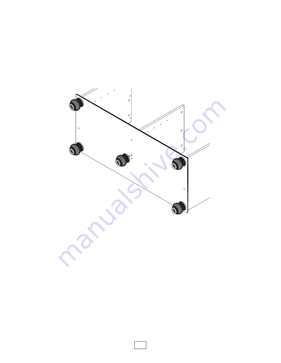
• Screw (5) base feet into the inserts in bottom (B).
B
Foot
8
3
Page 1: ...INSTRUCTION BOOKLET CONTAINS IMPORTANT SAFETY INFORMATION PLEASE READ AND KEEP FOR FUTURE REFERENCE ADULT ASSEMBLY REQUIRED Lot Numbers Date Purchased DO NOT RETURN YOUR UNIT TO THE STORE CONTACT US...
Page 2: ...ht item just as you need it NOTE ALL PARTS MAY NOT BE IDENTIFIED WITH LABELS Furniture Care Congratulations Broyhill is making every effort to conserve our precious resources Therefore certain reworke...
Page 3: ...shown smaller than actual size Note For reasons of manufacturing ef ciencies you may nd extra hardware and unused holes in parts CS Cam Stud 9 80180828 Base Foot 5 80182003 FD Felt Disc 2 Strips 80182...
Page 4: ...not be identi ed with labels but to help identify certain parts you may see one or more types of labeling One type is the peel off label and the other is an ink print on one of the un nished edges A D...
Page 5: ...0182053 O Back Panel 1 41 9 16 x 20 3 4 80182059 D Left Side 1 19 3 16 x 17 7 8 80182055 C Right Side 1 19 3 16 x 17 7 8 80182054 E Partition 1 19 3 16 x 14 5 8 80182056 F Adjustable Shelf 2 19 7 8 x...
Page 6: ...m housings CH into the holes in left side D right side C and partition E Cam Housing CH D C E CH CH CH CH CH CH CH CH CH Figure 1 Make sure arrow in cam housing is facing the hole in the edge of panel...
Page 7: ...rench B S4 D E C Attach bottom B to left side D right side C and partition E using S4 screws x 9 4MM hex wrench is provided Note Make sure heads of screws S4 are ush with bottom B Finished Edges Up 2...
Page 8: ...Screw 5 base feet into the inserts in bottom B B Foot 8 3...
Page 9: ...Screw cam studs CS x 9 into the holes as shown in top A CS Cam Studs CS A 9 4...
Page 10: ...tach top A to left side D right side C and partition E Lock cam housings with a half turn clockwise of a standard at head screwdriver Finished Edge Finished Edge Arrow 1 2 turn clockwise Do not overti...
Page 11: ...notch as shown even with the bottom edge of bottom B and pilot holes align with partition E Make sure panel O ts square and even side to side If it doesn t adjust unit into square by pushing or pulli...
Page 12: ...Push shelf pins into the holes at the height you desire in left side D partition E and right side C 7 12 Position the shelves on top of shelf pins 8 F F Finished Edge...
Page 13: ...clockwise Unlock Cam Housing Door H A Push up slightly on the front edge of top A to allow door to be placed upright Have a helper secure door while installing SEE STEPS 17 20 FOR DOORS H INSTALLATIO...
Page 14: ...and up in the upper runner guides to allow upper runner guides to insert into the guide track in top A Left Door H 10 Upper Runner Guide Place the lower runner guides in left door H into the back gui...
Page 15: ...nner guide to allow upper runner guide to insert into the guide track in top A SEE NEXT STEP TO LOCK OTHER UPPER RUNNER GUIDE IN PLACE B A Right Door H 11 Reposition left and right doors as shown to e...
Page 16: ...FD Felt Disc Peel the sticky backing and place 2 adhesive felt disc FD onto left and right doors H as shown FD 13 16...
Page 17: ...Decorative cover caps are provided to cover all exposed cam housings on nished panels Cover Caps 14 D E C 17...
Page 18: ...not exceed the recommended weight limits on the designated panels Exceeding these limits could cause sagging possibly resulting in failure of the panels or bodily injury IMPORTANT 15 lbs 95 lbs 25 lbs...
Page 19: ...That s it You ve nished assembling your TV Stand A touch up pen has been provided for any touch up needed MRP 80167922 0410 19...
Page 20: ...herraje en el piso preferiblemente sobre una alfombra tal como aparecen en la Lista de Piezas Esto le ayudar a localizar la pieza correcta seg n la necesite NOTA PUEDE SER QUE NO TODAS LAS PIEZAS HAYA...
Page 21: ...8 de pulgada para el herraje 4 S3 Tornillo de 3 pulgadas de cabeza arandela redonda 4 S4 Tornillo de 2 pulgadas de cabeza hexagonal 9 Clavo 40 Llave hexagonal de 4MM Llave hexagonal de 6MM Gu a corre...
Page 22: ...ral izquierdo 1 C Panel lateral derecho 1 E Partici n 1 1 Caja para el mecanismo de cierre CH Figura 1 Aseg rese de que la abertura en la caja para el mecanismo de cierre CH d hacia el agujero en el b...
Page 23: ...atas en los agujeros apropiados del fondo B seg n se muestran 5 S4 Tornillo de 2 pulgadas de cabeza hexagonal Llave hexagonal de 4MM Los bordes con acabado deber n dar hacia arriba Lado sin acabado Bo...
Page 24: ...e en el piso boca abajo seg n se muestra Coloque el panel posterior O sobre el mueble a ras del borde inferior del fondo B y con la muesca orientada tal como la mostramos los agujeros piloto deber n a...
Page 25: ...H 15 Gu a corredera para el riel superior Gu a corredera para el riel inferior Gu a corredera superior Parte superior de las puertas Tirador Puerta derecha H Puerta izquierda H Tirador Gu a corredera...
Page 26: ...s Pasos 17 20 para la instalaci n normal de las puertas H Importante Fije de nuevo las 9 cajas CH en los paneles D E y C d ndoles medio giro en sentido del reloj utilizando un destornillador normal de...
Page 27: ...ndan resultando posiblemente en la falla de los paneles o en lesiones personales ADVERTENCIA No use nunca este mueble con televisor que sea demasiado grande o pesado Tal uso puede resultar en lesiones...