III - 11
[3]
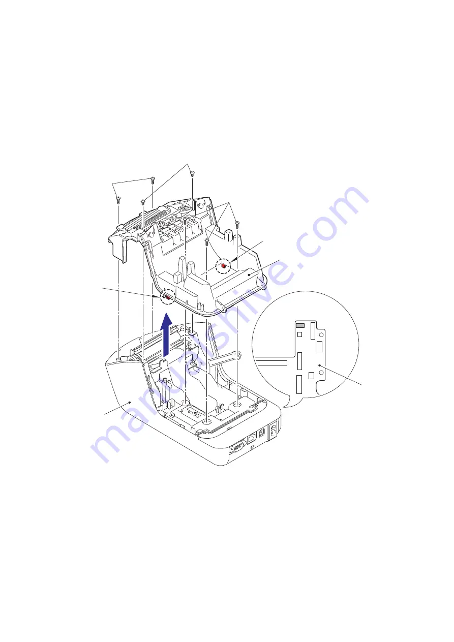
Disassembling the Upper Cover and the Under Cover
(1) Disconnect the flat cable (CN4) of the tape sensor PCB ASSY from the main PCB
ASSY.
(2) Remove the two screws A and five screws B from the upper cover.
(3) Release the two hooks to disassemble the upper cover and the under cover.
NOTE:
The screws A are screw, bind M2.6x4. The screws B are taptite, bind B
M2.6x8.
Fig. 3.4-12 Disassembling the Upper Cover and the Under Cover (1)
CN4
Under cover
Hook
Screws B
Screws B
Screws A
Hook
Upper cover
Main PCB ASSY
<Bottom side view>


