CHAPTER 7 DISASSEMBLY & RE-ASSEMBLY
7-56
4.7.3
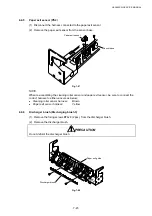
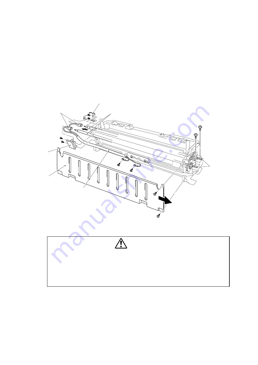
Fusing heater lamp (Fusing heater 3 (US)(EC))
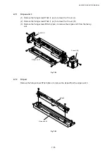
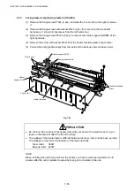
(1) Remove the fixing screw ST3x6 (2 pcs.) and slide the F cover (B) to the right to remove
it.
(2) Remove the fixing screws with washer M3x6 (2 pc.) from securing the two heater
harnesses. (1st and 3rd harnesses from the left hand side.)
(3) Remove the fixing screws ST3x6 (4 pcs.) to remove the heater support (HR/BR) at the
right hand side.
(4) Remove the screw with washer M3x6 from the heater electrode plate of each lamp.
(5) Pull out the fusing heater lamps from the inside of the back-up roller and fuser roller.
Fig. 7-86
PRECAUTION
x
Do not touch the surface of the heater lamp with your hands, the small traces of oil you
leave on the lamp will affect the life of the lamp.
x
The wattage of the heater lamp is different between the fuser roller and the back-up roller.
The wattage is marked on the insulator of the lamp electrode.
Fuser
roller:
560W
Back-up roller : 420W
NOTE:
When installing the new fusing unit into the printer, you have to wait approximately for 30
minutes after the unit is installed to allow the fusing oil to circulate in the unit.
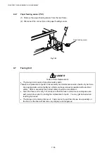
Heater
support (HR)
Terminal (L)
Fusing heater lamp
F cover (B)
Heater harness
Heater support (BR)
Heater electrode
plate
Summary of Contents for HL-3450CN Series
Page 15: ...HL 3450CN SERVICE MANUAL xiii 3 Rating Label For US For Europe 4 Operation Label 5 Jam Label ...
Page 17: ...HL 3450CN SERVICE MANUAL CHAPTER 1 PRODUCT OUTLINE ...
Page 27: ...HL 3450CN SERVICE MANUAL CHAPTER 2 SPECIFICATIONS ...
Page 39: ...CHAPTER 3 INSTALLATION ...
Page 54: ...HL 3450CN SERVICE MANUAL CHAPTER 4 STRUCTURE OF SYSTEM COMPONENTS ...
Page 104: ...HL 3450CN SERVICE MANUAL 4 51 Main PCB Circuit Diagram 1 8 CODE B512137CIR 1 8 LJ8907001 NAME ...
Page 106: ...HL 3450CN SERVICE MANUAL 4 53 Main PCB Circuit Diagram 3 8 CODE B512137CIR 3 8 LJ8907001 NAME ...
Page 108: ...HL 3450CN SERVICE MANUAL 4 55 Main PCB Circuit Diagram 5 8 CODE B512137CIR 5 8 LJ8907001 NAME ...
Page 110: ...HL 3450CN SERVICE MANUAL 4 57 Main PCB Circuit Diagram 7 8 CODE B512137CIR 7 8 LJ8907001 NAME ...
Page 126: ...HL 3450CN SERVICE MANUAL CHAPTER 5 CONTROL PANEL OPERATION ...
Page 173: ...HL 3450CN SERVICE MANUAL CHAPTER 6 PERIODIC MAINTENANCE ...
Page 208: ...CHAPTER 7 DISASSEMBLY RE ASSEMBLY ...
Page 264: ...HL 3450CN SERVICE MANUAL CHAPTER 8 TROUBLESHOOTING ...
Page 310: ...HL 3450CN SERVICE MANUAL 8 47 5 IMAGE FAILURE 1 2 3 4 5 6 7 8 9 a 9 b 10 11 12 13 14 ...
Page 311: ...CHAPTER 8 TROUBLESHOOTING 8 48 15 a 15 b 16 17 18 19 20 21 22 23 24 25 26 27 28 244m m 29 ...

