Brother HL-2260 Service Manual Download Page 178

5-28

Confidential

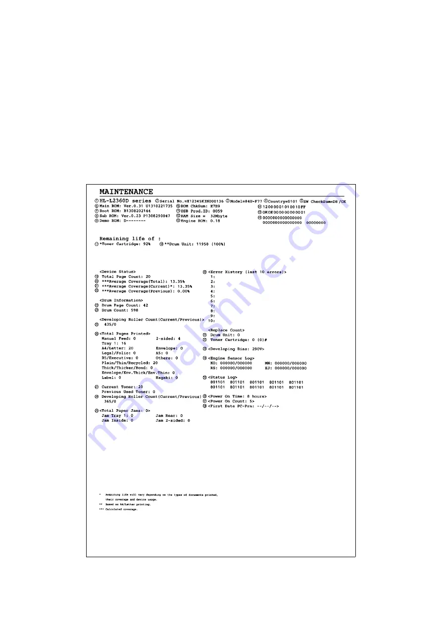
1.3.16 Print maintenance information (function code: 77)

<Function>

This function is used to print the maintenance information, such as remaining amount of 

consumables, the number of replacements, and counter information.

<Operating Procedure>

(1) Press the [▲] or [▼] key in the initial state of maintenance mode to display 

"MAINTENANCE 77" on the LCD, and press the [OK] key. Printing maintenance 

information starts.

When printing is completed, the machine returns to the initial state of maintenance 

mode.

Maintenance information

Fig. 5-10

Summary of Contents for HL-2260

Page 1: ...2300D L2305W L2315DW L2320D L2340DW L2360DN L2360DW L2365DW 2260 2260D 2560DN L2321D L2361DN L2366DW Read this manual thoroughly before maintenance work Keep this manual in a convenient place for quick and easy reference at all times April 2014 SM PRN096 84UF 7 ...

Page 2: ...d Access are registered trademarks of the Wi Fi Alliance WPA WPA2 Wi Fi Protected Setup Wi Fi Protected Setup logo and Wi Fi Direct are trademarks of the Wi Fi Alliance FLICKR is a registered trademark of Yahoo Inc AOSS is a trademark of Buffalo Inc Android Google Cloud Print Google Drive Google Play and Picasa Web Albums are trademarks of Google Inc Use of this trademark is subject to Google Perm...

Page 3: ...the following vendors 1983 1998 PACIFIC SOFTWORKS INC ALL RIGHTS RESERVED 2008 Devicescape Software Inc All rights reserved This product includes the KASAGO TCP IP software developed by ZUKEN ELMIC Inc Other Information FlashFX is a registered trademark of Datalight Inc FlashFX Copyright 1998 2010 Datalight Inc U S Patent Office 5 860 082 6 260 156 FlashFX Pro is a trademark of Datalight Inc Relia...

Page 4: ...5 Main Components 2 8 3 ERROR INDICATIONS 2 9 3 1 Error Codes 2 9 3 2 Error Messages 2 16 3 3 LED Display LED Models 2 19 3 3 1 LED display when operator call occurs 2 19 3 3 2 LED display when service call occurs 2 22 4 TROUBLESHOOTING 2 26 4 1 Error Cause and Remedy 2 26 4 2 Troubleshooting for Paper Feeding Problems 2 47 4 2 1 No paper is fed from paper tray 2 47 4 2 2 No paper is fed from manu...

Page 5: ...ner cartridge cannot be recognized 2 71 4 7 3 Error message prompting toner cartridge replacement does not disappear 2 72 4 7 4 Drum error 2 72 4 7 5 Error message prompting drum replacement does not disappear 2 72 4 8 Troubleshooting for Fuser Unit Problems 2 73 4 8 1 Fuser unit failure 2 73 4 9 Troubleshooting for Laser Unit Problems 2 73 4 9 1 Laser unit failure 2 73 4 10 Troubleshooting for PC...

Page 6: ... 3 39 9 21 Main Frame L ASSY 3 40 9 22 Main Motor 3 42 9 23 Fuser Gear 67R 40R 3 44 9 24 Eject Sensor PCB ASSY 3 45 9 25 Registration Front rear Actuator Holder ASSY 3 47 CHAPTER 4 ADJUSTING AND UPDATING SETTINGS AS REQUIRED AFTER PARTS REPLACEMENT 1 IF YOU REPLACE THE MAIN PCB ASSY 4 1 1 1 Setting Default Paper Size LED Models Setting by Spec LCD Models 4 2 1 2 Installing Firmware Sub Firmware De...

Page 7: ... end print start position on second side when duplex printing function code 45 5 17 1 3 11 Continuous print test function code 67 5 18 1 3 12 Print frame pattern single side printing function code 69 5 22 1 3 13 Print frame pattern duplex printing function code 70 5 23 1 3 14 Print test pattern function code 71 5 24 1 3 15 Setting by spec function code 74 5 26 1 3 16 Print maintenance information ...

Page 8: ...ice personnel 5 42 2 OTHER SERVICE FUNCTIONS 5 43 2 1 Engine Error Ignore Mode LCD models only 5 43 2 2 Change USB No Return Value Adjust Left end Print Start Position on Second Side when Duplex Printing LCD models only 5 44 2 3 Print Printer Settings 5 45 CHAPTER 6 WIRING DIAGRAM 1 WIRING DIAGRAM 6 1 CHAPTER 7 PERIODICAL MAINTENANCE 1 PERIODICAL REPLACEMENT PARTS 7 1 APPENDIX 1 SERIAL NUMBERING S...

Page 9: ...MPORTANT indicates a potentially hazardous situation which if not avoided may result in damage to property or loss of product functionality Prohibition icons indicate actions that must not be performed Electrical Hazard icons alert you to possible electrical Shock Fire hazard icons alert you to the possibility of fire Hot Surface icons warn you not to touch product parts that are hot Note Notes te...

Page 10: ...duct including for routine maintenance such as cleaning make sure you have unplugged the power cord from the AC power outlet as well as Ethernet RJ 45 cables Network models only from the product Never push objects of any kind into this product through cabinet slots since they may touch dangerous voltage points or short out parts DO NOT handle the plug with wet hands DO NOT use this product during ...

Page 11: ...T use the product if the power cord is frayed or damaged Doing so may cause an electrical shock or fire Brother strongly recommends that you DO NOT use any type of extension cord DO NOT drop any metallic hardware or any type of liquid on the power plug of the product It may cause an electrical shock or a fire DO NOT put a toner cartridge or a toner cartridge and drum unit assembly into a fire It c...

Page 12: ...of the laser unit ACHTUNG Im Falle von Störungen der Lasereinheit muß diese ersetzt werden Das Gehäuse der Lasereinheit darf nicht geöffnet werden da sonst Laserstrahlen austreten können HOT SURFACE After you have just used the product some internal parts of the product will be extremely hot Wait at least ten minutes for the product to cool down before you touch the internal parts of the product L...

Page 13: ...er or other reflective object in the path of the laser beam Be sure to take off any personal accessories such as watches and rings before working on the machine A reflected beam though invisible can permanently damage the eyes Since the beam is invisible the following caution in print is attached on the laser unit In print ...

Page 14: ... Less than 26 seconds at 73 4F 23 C First print time From Ready mode Less than 8 5 seconds at 73 4F 23 C From Sleep mode Less than 17 5 seconds at 73 4F 23 C CPU ARM9 266 MHz Dimensions W x D x H Carton size 441 x 286 x 504 mm 17 4 x 11 3 x 19 8 inch 524 x 451 x 291 mm 20 6 x 17 8 x 11 5 inch Machine size 356 x 360 x 183 mm 14 0 x 14 2 x 7 2 inch Weights with Carton 7 7 kg 17 0 lb 7 9 kg 17 4 lb f...

Page 15: ...or China 524 x 451 x 291 mm 20 6 x 17 8 x 11 5 inch for China Machine size 356 x 360 x 183 mm 14 0 x 14 2 x 7 2 inch Weights with Carton 7 9 kg 17 4 lb Except for China Europe 8 0 kg 17 7 lb for China Europe without Carton with toner drum 6 8 kg 15 0 lb Except for China Europe 6 7 kg 14 8 lb for China 6 9 kg 15 2 lb for Europe without Carton nor toner drum 5 9 kg 13 0 lb Except for China 5 8 kg 12...

Page 16: ... L2360DW HL L2365DW HL L2366DW Wired network Network node type N A NC 8700h Wireless network Network node type N A NC 8300w N A NC 8300w Specifications are subject to change without notice Model All models Machine life 50 000 pages A4 LTR or 5 years MTBF 4 000 hours MTTR 0 5 hours Maximum monthly volume Up to 10 000 pages Parts life Fuser Unit Up to 50 000 pages Laser Unit Up to 50 000 pages PF ki...

Page 17: ...tancy Approximately 12 000 pages 1 page job The life expectancy varies according to the use condition Shelf life 2 years The shelf life of toner cartridge and drum unit is guaranteed under the normal condition as below Temperature Normal condition 0 to 40 C Storage condition at the temperature of 40 to 50 C Up to 5 days Storage condition at the temperature of 20 to 0 C Up to 5 days Humidity Normal...

Page 18: ...ter size one sided pages in accordance with ISO IEC 19752 Shelf life 2 years without opening 6 months after opening Drum unit Life expectancy Approximately 12 000 pages 1 page job The life expectancy varies according to the use condition Shelf life 2 years The shelf life of toner cartridge and drum unit is guaranteed under the normal condition as below Temperature Normal condition 0 to 40 C Storag...

Page 19: ... or disconnecting the cable Be sure to hold the connector 3 Static electricity charged in your body may damage electronic parts Before handling the PCBs touch a metal section of the machine to discharge static electricity When transporting PCBs be sure to wrap them in conductive sheets When replacing the PCBs wear a grounding wrist band and perform replacement on an antistatic mat Also take care n...

Page 20: ...ssive heat moisture or dust 4 Hold the machine level while moving it Be sure to move or lift the machine with two or more people Power supply 1 Power described on the rating label attached on the machine is supplied Power fluctuation should be within 10 of the rated voltage 2 The AC input power supply is within the regulated value 3 The cables and harnesses are connected correctly 4 The fuses are ...

Page 21: ...tion pad may cause paper feed problems If condensation has formed in the machine leave the machine for at least two hours until it reaches room temperature If the drum unit is unpacked soon after it is moved to a warm room from a cold location condensation may occur inside the unit which may cause printing failure Leave the drum unit for one or two hours until it reaches room temperature and then ...

Page 22: ...t Registration rear actuator Front side Registration front actuator Manual feed slot Paper dust cleaning roller Paper feed actuator Separation pad Separation roller Pick up roller Plate Duplex paper feed roller Pressure roller Duplex tray Heat roller Eject actuator Eject roller 1 Back cover Registration roller ...

Page 23: ...2 5 Confidential 2 2 Paper Feeding Fig 2 2 Eject to output tray Feed from manual feed slot Front side Duplex path Back side Eject to back side ...

Page 24: ... sensor Detects paper pass and adjusts the writing start position for the paper Detects paper jams in the front or center section of the machine Detects the rear edge of the paper to identify the paper size Heat roller Pressure roller Fuses the toner transferred to paper by heat and pressure and feeds paper to the eject roller 1 Eject actuator Eject sensor Determines whether paper is ejected from ...

Page 25: ...ion rear sensor Registration front rear sensor PCB Registration front sensor Panel PCB WLAN LED Power key Power key LCD Fan Front cover sensor Fuser unit Registration clutch T1 clutch Main motor LD PCB BD sensor Polygon motor Back cover duplex tray sensor Paper feed sensor Paper feed sensor PCB LCD models Wireless LAN PCB WLAN model only WLAN model only Panel PCB Toner LED Drum LED Paper LED LED m...

Page 26: ...Top cover ASSY LCD models Fuser unit LVPS shield plate cover LVPS insulation sheet Low voltage power supply PCB ASSY Fan High voltage power supply PCB ASSY Air duct Filter Laser unit Wireless LAN PCB Roller holder ASSY Main PCB ASSY T1 clutch Registration clutch New toner sensor PCB ASSY Motor drive sub ASSY Fuser gear 67R 40R Eject sensor PCB ASSY Registration front rear actuator holder ASSY ...

Page 27: ...mperature the side thermistor detected a temperature higher than the specified temperature 2 30 0205 050C When the center thermistor of the fuser unit was higher than the idle temperature the side thermistor detected a temperature lower than the specified temperature 2 30 0206 050D 0207 050F An error occurred in the fuser unit 2 30 0208 0600 A communication error occurred between the ASIC controll...

Page 28: ...04 2409 1100 2501 1200 2502 1300 2503 1400 2504 1500 2601 1C00 2602 1D01 2603 1D02 2604 1D03 2605 1D04 2701 1E01 2702 1E02 2703 2001 2801 2002 2802 2003 2803 2004 2804 2005 2805 2006 2806 2101 2901 2102 2902 2103 2903 2104 2904 2105 2905 2201 2906 2202 2A01 2203 2A02 2204 2A03 2205 2B01 2206 2B02 2207 2C01 2301 2C02 2302 2D01 2401 2E01 ...

Page 29: ... 3002 4800 3003 4900 3102 4A00 3202 4B01 Dot count or develop roller counter of the toner is reaching the upper limit 2 33 3301 4B02 3302 4B03 3401 4B04 3402 4C01 Dot count or develop roller counter of the toner has reached the upper limit in the toner stop mode 2 34 3501 4C02 3601 4C03 3701 4C04 3702 4C05 3703 4D01 Dot count or develop roller counter of the toner has reached the upper limit in th...

Page 30: ... the fuser unit This message is displayed for approximately 15 minutes when the machine is restarted after error code 6901 has occurred 2 37 5702 6A00 Detected discharge that may be attributable to dirty corona wire on the drum unit 2 38 5801 6B01 5802 6B02 5902 6B03 5A02 6B04 5B02 6B0A 5C02 6C01 6001 The front cover sensor detected that the front cover was open 2 35 6C02 6002 6C03 6003 6C04 6004 ...

Page 31: ...pass 2 40 8506 7301 8507 7400 8508 7401 8601 7501 8602 7502 8603 7601 8604 7602 8701 7700 The registration front sensor does not detect paper pass within the specified time after the first side was printed in duplex printing mode 2 41 8702 7701 8703 7702 8801 7703 8802 7704 8901 7705 8902 7801 8903 The back cover duplex tray sensor detected that the cover was open when duplex printing is started B...

Page 32: ...5 8F02 9801 8F03 9802 9001 9803 9002 When printing from the paper tray the size of paper set in the paper tray does not match the size specified by the driver 2 44 9804 9003 9901 9004 9902 9005 9903 9102 9A01 9103 9A02 9104 9A03 9105 9C01 9200 9C02 9301 9C03 9302 When printing from the paper tray the paper feed sensor detected that there was no paper set in the paper tray 2 44 9C06 9303 9C07 9304 ...

Page 33: ...n the flash ROM on the main PCB 2 45 B700 E900 B800 EC00 B900 F900 The country code was not entered correctly 2 46 BA00 FA01 BB00 FA02 BC00 FA03 BD00 FB01 BE00 FB02 BF00 FB03 C001 FB04 C002 FB05 C003 FB06 C004 FB07 C700 There is insufficient memory to expand PC print data 2 45 FB08 C800 FB09 C900 FB0A CA00 FB0B D100 FB0C D200 FB0D D800 FB0F D900 FC01 DA00 FC02 DB00 FC03 E000 An error occurred in t...

Page 34: ...re there is no paper jammed inside the machine and close the Back Cover then press Go The eject sensor was ON when the power switch was turned ON 7C00 2 41 Drum Slide the Green tab on Drum Unit Detected discharge that may be attributable to dirty corona wire on the drum unit 6A00 2 38 Drum End Soon The number of rotations of the drum unit is reaching the upper limit 4000 2 33 Jam 2 sided Pull out ...

Page 35: ... Cartridge The new toner sensor detected that the toner cartridge was not set 6101 2 36 Out of Memory Press Go for 2 seconds There is insufficient memory to expand PC print data C700 2 45 Print Overrun First side printing started before finishing receiving the second side data in duplex printing mode due to the insufficient memory 8000 2 42 Print Unable Printing related error Refer to error code R...

Page 36: ...istration rear sensor detected that the paper fed was smaller or larger than the specified size in duplex printing mode 8A01 2 43 Size Mismatch Load paper and press Go When printing from the paper tray the size of paper set in the paper tray does not match the size specified by the driver 9002 2 44 Toner Ended Open the Front Cover replace Toner Cartridge The toner cartridge has reached the upper l...

Page 37: ...feed sensor detected paper pass 7300 2 40 The registration front sensor does not detect paper pass within the specified time after the first side was printed in duplex printing mode 7700 2 41 The eject sensor was ON when the power switch was turned ON 7C00 2 41 First side printing started before finishing receiving the second side data in duplex printing mode due to the insufficient memory 8000 2 ...

Page 38: ...1 2 34 Dot count or develop roller counter of the toner has reached the upper limit in the toner stop mode 4C01 2 34 The toner cartridge has reached the upper limit in the toner continuous printing mode 4E01 2 34 Detected discharge that may be attributable to dirty corona wire on the drum unit 6A00 2 38 The number of rotations of the drum unit is reaching the upper limit 4000 2 33 LED Type of prob...

Page 39: ...ray 9302 2 44 The new toner sensor could not detect the new toner cartridge correctly 4F01 2 34 The new toner sensor detected that the toner cartridge was not set 6101 2 36 An error occurred in the ROM check sum E000 2 45 Program error E100 2 45 An error occurred during access to the DRAM in the main PCB ASSY E500 2 45 Read error in the flash ROM on the main PCB E702 2 45 The side thermistor of th...

Page 40: ...em Error codes Refer to Cannot detect the synchronized signal of the main motor The speed of the main motor does not stabilize within the specified time 0201 2 26 An error occurred in the high voltage power supply PCB ASSY when the machine was in the ready state 0B02 2 32 A communication error occurred between the ASIC controlled by engine and the motor driver 0600 2 31 An error occurred in the hi...

Page 41: ...0 times 6F00 2 39 The center thermistor of the fuser unit has not reached the specified temperature within the specified time after it was heated normally to the certain level 0502 2 28 The hardware detected a temperature error through the center thermistor or the side thermistor of the fuser unit 050A 2 30 An error occurred in the fuser unit 050F 2 30 LED Press Go once Press Go twice Type of prob...

Page 42: ...it This message is displayed for approximately 15 minutes when the machine is restarted after error code 6901 has occurred 6902 2 37 The center thermistor of the fuser unit detected a temperature higher than the specified value 0503 2 28 After the heat unit was heated normally the center thermistor of the fuser unit detected a temperaturelower than the specified value 0504 2 28 LED Press Go once P...

Page 43: ...ermistor of the fuser unit was lower than the idle temperature the side thermistor detected a temperature higher than the specified temperature 050B 2 30 When the center thermistor of the fuser unit was higher than the idle temperature the side thermistor detected a temperaturelower than the specified temperature 050C 2 30 The center thermistor of the fuser unit has not reached the specified tempe...

Page 44: ... 1 Connection failure of the main motor flat cable Reconnect the main motor flat cable 2 Connection failure of the LVPS harness Reconnect the LVPS harness 3 Damaged fuser gear Replace the fuser gear 4 Main motor failure Replace the main motor 5 Damaged fuser unit Replace the fuser unit 6 Low voltage power supply PCB failure Replace the low voltage power supply PCB ASSY 7 Damaged part in motor driv...

Page 45: ...chronized signal of the polygon motor for the laser unit first time Print Unable 03 Turn the power off and then back on again Print Unable 03 Turn the power off and then back on again Print Unable 04 Turn the power off and then back on again Print Unable 04 Turn the power off and then back on again Step Cause Remedy 1 Connection failure of the laser unit flat cable Reconnect the laser unit flat ca...

Page 46: ...an the specified value Error code 0504 After the heat unit was heated normally the center thermistor of the fuser unit detected a temperature lower than the specified value Error code 0505 The center thermistor of the fuser unit detected a temperature rise greater than the specified value within the specified time Print Unable 05 Turn the power off and then back on again Print Unable 05 Turn the p...

Page 47: ... thermistor harness of the fuser unit Reconnect the center or side thermistor harness of the fuser unit 2 Connection failure of the fuser unit heater harness Reconnect the fuser unit heater harness 3 Connection failure of the eject sensor PCB flat cable Reconnect the eject sensor PCB flat cable 4 Connection failure of the LVPS harness Reconnect the LVPS harness 5 Eject sensor PCB failure Replace t...

Page 48: ...le 05 Turn the power off and then back on again Print Unable 05 Turn the power off and then back on again User Check Turn OFF the power switch After several seconds turn ON the power again and check that this error is reset Step Cause Remedy 1 Connection failure of the center or side thermistor harness of the fuser unit Reconnect the center or side thermistor harness of the fuser unit 2 Connection...

Page 49: ...p Cause Remedy 1 Low voltage power supply PCB failure Replace the low voltage power supply PCB ASSY Refer to 1 3 20 Reset irregular power supply detection counter of low voltage power supply PCB function code 88 in Chapter 5 to reset the irregular power supply detection counter 2 Main PCB failure Replace the main PCB ASSY Note The irregular power supply detection error of the low voltage power sup...

Page 50: ...e Reconnect the HVPS flat cable 3 Fan failure Replace the fan 4 Low voltage power supply PCB failure Replace the low voltage power supply PCB ASSY 5 High voltage power supply PCB failure Replace the high voltage power supply PCB ASSY 6 Main PCB failure Replace the main PCB ASSY Print Unable 0B Turn the power off and then back on again Print Unable 0B Turn the power off and then back on again User ...

Page 51: ...B01 Dot count or develop roller counter of the toner is reaching the upper limit Drum End Soon Replace Drum User Check Prepare a new drum unit Step Cause Remedy 1 Replace the drum unit with a new one and reset the drum counter If the error display is not cleared the main PCB is faulty Replace the main PCB ASSY Toner Low User Check Prepare a new toner cartridge Step Cause Remedy 1 Main PCB failure ...

Page 52: ... If the error display is not cleared after replacing the toner cartridge with a new one the main PCB is faulty Replace the main PCB ASSY Cartridge Error Put the Toner Cartridge back in User Check Replace the toner cartridge with a new one again If the machine is on the uneven surface place it on a level surface Step Cause Remedy 1 Connection failure of the new toner sensor PCB flat cable Reconnect...

Page 53: ...r supply PCB ASSY 3 Main PCB failure Replace the main PCB ASSY Cover is Open Close the Fuser Cover which can be found behind the Back Cover of the machine User Check Close the fuser cover Step Cause Remedy 1 Eject actuator coming off or caught in sections of the machine Reattach the eject actuator 2 Fuser cover attachment failure Reattach the fuser cover 3 Connection failure of the eject sensor PC...

Page 54: ...Reattach the new toner actuator 2 Connection failure of the new toner sensor PCB flat cable Reconnect the new toner sensor PCB flat cable 3 Connection failure of the panel PCB flat cable Reconnect the panel PCB flat cable 4 New toner sensor PCB failure Replace the new toner sensor PCB ASSY 5 Panel PCB failure Replace the panel PCB ASSY 6 Main PCB failure Replace the main PCB ASSY Cooling Down Wait...

Page 55: ... Remedy 1 Connection failure of each fuser unit harness Reconnect each harness of the fuser unit 2 Connection failure of the eject sensor PCB flat cable Reconnect the eject sensor PCB flat cable 3 Fuser unit failure Replace the fuser unit 4 Eject sensor PCB failure Replace the eject sensor PCB ASSY 5 Low voltage power supply PCB failure Replace the low voltage power supply PCB ASSY 6 Main PCB fail...

Page 56: ... two to three times to clean the corona wire Clean the terminal of the drum unit Replace the drum unit Step Cause Remedy 1 Dirt on the high voltage power supply PCB terminal Clean the electrodes of the machine 2 High voltage electrodes attachment failure Check if the problem disappears after pressing each electrode If not reattach the electrodes 3 High voltage power supply PCB failure Replace the ...

Page 57: ...over pull out the Drum Unit completely and remove the jammed paper User Check Remove the jammed paper Step Cause Remedy 1 Foreign object inside the machine Remove the foreign object 2 Connection failure of the eject sensor PCB flat cable Reconnect the eject sensor PCB flat cable 3 Eject actuator coming off or caught in sections of the machine Reattach the eject actuator 4 Fuser cover attachment fa...

Page 58: ...stem Replace the main frame L ASSY 7 Main PCB failure Replace the main PCB ASSY Jam Tray 1 Remove the jammed paper from Tray 1 User Check Remove the jammed paper Close the paper tray correctly Step Cause Remedy 1 Foreign object in the front section of the paper tray Remove the foreign object 2 Paper dust cleaning roller attachment failure Reattach the paper dust cleaning roller 3 Connection failur...

Page 59: ...m of the paper tray Remove the foreign object 3 Back cover attachment failure Reattach the back cover 4 Fuser cover attachment failure Reattach the fuser cover 5 Duplex tray failure Replace the duplex tray 6 Damaged gears in the feeding system Replace the main frame L ASSY 7 Main PCB failure Replace the main PCB ASSY Cover is Open Make sure there is no paper jammed inside the machine and close the...

Page 60: ... Print the print data stored in the memory The size of printing data per page is too big Change the printing contents to reduce the data size Switch to single side printing Step Cause Remedy 1 Main PCB failure Replace the main PCB ASSY 2 sided Disabled Close the Back Cover of the machine 2 sided Disabled Close the Back Cover of the machine User Check Close the back cover correctly Step Cause Remed...

Page 61: ... rear actuator holder ASSY 3 Main PCB failure Replace the main PCB ASSY Manual Feed Load paper User Check Set paper in the manual feed slot Step Cause Remedy 1 Registration front actuator caught in some sections of the machine Reattach the registration front actuator 2 Connection failure of the registration rear sensor harness Reconnect the registration front rear sensor PCB harness 3 Connection f...

Page 62: ...tion rear sensor failure Replace the registration front rear actuator holder ASSY 3 Main PCB failure Replace the main PCB ASSY No Paper Load paper User Check Set paper in the paper tray Step Cause Remedy 1 Connection failure of the paper feed sensor harness Reconnect the paper feed sensor harness ASSY 2 Paper feed actuator caught in sections of the machine Reattach the paper feed actuator 3 New to...

Page 63: ... Press Go for 2 seconds User Check Print the print data stored in the memory Divide the print data and print them separately Step Cause Remedy 1 Main PCB failure Replace the main PCB ASSY Print Unable E0 Turn off and on Print Unable E1 Turn off and on User Check Install the latest firmware Step Cause Remedy 1 Main PCB failure Replace the main PCB ASSY Print Unable E5 Turn the power off and then ba...

Page 64: ...or code F900 The country code was not entered correctly Machine Error F9 Step Cause Remedy 1 The power was turned OFF while function code 74 was running Reenter the country code 2 Main PCB failure Replace the main PCB ASSY ...

Page 65: ...2 Attachment failure of the roller holder ASSY Reattach the roller holder ASSY correctly 3 Connection failure of the main motor flat cable Reconnect the main motor flat cable 4 Connection failure of the paper feed sensor harness Reconnect the paper feed sensor harness ASSY 5 Paper feed actuator coming off Reattach the paper feed actuator 6 Connection failure of the new toner sensor PCB flat cable ...

Page 66: ... sensor PCB harness Reconnect the registration front sensor PCB harness 5 Connection failure of the HVPS flat cable Reconnect the HVPS flat cable 6 Registration clutch failure Replace the registration clutch 7 Registration front sensor failure Replace the registration front rear actuator holder ASSY 8 HVPS flat cable breakage Replace the HVPS flat cable 9 Main motor failure Replace the main motor ...

Page 67: ... guide according to the paper size Check that the thickness of the paper is 60 to 105 g m2 60 to 163 g m2 for manual feed slot Check that the paper is not damp Check that there is no dust stuck to the fuser unit Check that the type of paper is appropriate Step Cause Remedy 1 Fuser unit failure Replace the fuser unit 2 Damaged gears in the ejecting system Replace the main frame L ASSY ...

Page 68: ...paper is appropriate Clean the pick up roller Check that the green envelope lever is not lowered on only one side Replace the drum unit Replace the toner cartridge Step Cause Remedy 1 Pinch spring of the paper tray coming off Reattach the pinch spring of the paper tray 2 Tray pinch spring of the machine side coming off Reattach the tray pinch spring of the machine side Refer to the figure below 3 ...

Page 69: ...in PCB failure Replace the main PCB ASSY User Check Close the back cover completely Set the duplex tray correctly Set the driver setting to duplex printing Use A4 or Letter paper specified by the manufacturer Step Cause Remedy 1 Eject actuator coming off Reattach the eject actuator 2 Back cover failure Replace the back cover 3 Back cover duplex tray sensor or eject sensor failure Replace the eject...

Page 70: ...t actuator 4 Connection failure of the registration front rear sensor PCB harness Reconnect the registration front rear sensor PCB harness 5 Connection failure of the registration clutch harness Reconnect the registration clutch harness 6 Connection failure of the HVPS flat cable Reconnect the HVPS flat cable 7 HVPS flat cable breakage Replace the HVPS flat cable 8 Registration front sensor failur...

Page 71: ...rness 3 Registration front actuator coming off Reattach the registration front actuator 4 Connection failure of the registration clutch harness Reconnect the registration clutch harness 5 Connection failure of the HVPS flat cable Reconnect the HVPS flat cable 6 HVPS flat cable breakage Replace the HVPS flat cable 7 Registration front sensor failure Replace the registration front rear actuator hold...

Page 72: ...ff Reattach the eject actuator 3 Connection failure of the eject sensor PCB flat cable Reconnect the eject sensor PCB flat cable 4 Connection failure of the registration clutch harness Reconnect the registration clutch harness 5 Fuser cover attachment failure Reattach the fuser cover 6 Registration clutch failure Replace the registration clutch 7 Eject sensor failure Replace the eject sensor PCB A...

Page 73: ...ble 4 Fuser cover attachment failure Reattach the fuser cover 5 Eject sensor failure Replace the eject sensor PCB ASSY 6 Damaged gears in the ejecting system Replace the main frame L ASSY 7 Fuser unit failure Replace the fuser unit 8 Main PCB failure Replace the main PCB ASSY User Check Flip over the paper in paper tray or rotate the paper 180 Check that the thickness of the paper is 60 to 105 g m...

Page 74: ...Image distortion 2 59 All black 2 60 Dirt on the paper 2 60 Vertical streaks 2 61 Black vertical streaks on a light background 2 62 Horizontal streaks 2 62 White vertical streaks 2 63 White horizontal streaks 2 63 Faint print 2 63 White spots 2 64 Single colored dot or dirt 2 65 Black band 2 65 Downward fogging of solid color 2 66 Horizontal lines 2 66 Ghost 2 66 Fogging 2 67 ...

Page 75: ...ectrodes of the drum unit and those of the machine Refer to Fig 2 5 and Fig 2 6 2 Dirt on the electrodes of the toner cartridge and those of the machine Clean the electrodes of the toner cartridge and those of the machine Refer to Fig 2 5 and Fig 2 6 3 Wrong adjusted value of the laser unit entered Refer to 1 3 Setting Serial Number and Entering Adjusted Value of Laser Unit in Chapter 4 and enter ...

Page 76: ...of the laser unit correctly 4 Dirt on the electrodes of the high voltage power supply PCB Clean the electrodes of the machine Refer to Fig 2 6 5 Fuser unit failure Replace the fuser unit 6 High voltage power supply PCB failure Replace the high voltage power supply PCB ASSY 7 Main PCB failure Replace the main PCB ASSY 8 Laser unit failure Replace the laser unit User Check Check the usage environmen...

Page 77: ...he toner cartridge and those of the machine Refer to Fig 2 5 and Fig 2 6 3 Connection failure of the laser unit flat cable Reconnect the laser unit flat cable 4 Laser unit attachment failure Reattach the laser unit 5 Laser unit flat cable failure Replace the laser unit flat cable 6 Dirt on the electrodes of the high voltage power supply PCB Clean the electrodes of the machine Refer to Fig 2 6 7 La...

Page 78: ...2 6 3 Laser unit flat cable failure Replace the laser unit flat cable 4 Dirt on the electrodes of the high voltage power supply PCB Clean the electrodes of the machine Refer to Fig 2 6 5 High voltage power supply PCB failure Replace the high voltage power supply PCB ASSY 6 Laser unit failure Replace the laser unit 7 Main PCB failure Replace the main PCB ASSY User Check This problem may disappear a...

Page 79: ...or Replace the drum unit with a new one Replace the toner cartridge with a new one Step Cause Remedy 1 Dirt on the paper feed system Wipe off the dirt 2 FG harnesses or FG plate attachment failure not grounded correctly Retighten the screws to secure the FG harnesses or FG plate Fix the bent tray ground spring of the paper tray Refer to the figure below 3 Dirt on the fuser unit Replace the fuser u...

Page 80: ...ilure Replace the laser unit User Check Clean the corona wire of the drum unit This problem may disappear after printing multiple sheets of paper Refer to the User s Guide to remove the dirt from the exposure drum using a cotton applicator Replace the drum unit with a new one Replace the toner cartridge with a new one Step Cause Remedy 1 Dirty charge electrodes Clean the electrodes of the drum uni...

Page 81: ...ser Check This problem may disappear after printing multiple sheets of paper Replace the drum unit with a new one Replace the toner cartridge with a new one Step Cause Remedy 1 Dirty charge electrodes Clean the electrodes of the drum unit and those of the machine Refer to Fig 2 5 and Fig 2 6 2 Scratch or dirt on the fuser unit Replace the fuser unit 3 High voltage power supply PCB failure Replace ...

Page 82: ...it with a new one Replace the toner cartridge with a new one Step Cause Remedy 1 Accumulated paper dust Remove the paper dust cleaning roller cover and get rid of the paper dust in the area described in Fig 2 7 2 Clogged filter Clean the filter 3 Scratch or dirt on the fuser unit Replace the fuser unit 4 High voltage power supply PCB failure Replace the high voltage power supply PCB ASSY ...

Page 83: ...lers Refer to the table below and determine the cause based on the diameter of the rollers or the pitch at which defects appear on the image Part name Pitch at which defects appear in the image Develop roller 32 4 mm Exposure drum 94 2 mm Heat roller in the fuser unit 78 5 mm Pressure roller in the fuser unit 78 5 mm User Check Clean the corona wire of the drum unit Return the corona wire cleaning...

Page 84: ...w one Step Cause Remedy 1 Dirty charge electrodes Clean the electrodes of the drum unit and those of the machine Refer to Fig 2 5 and Fig 2 6 2 Scratch or dirt on the fuser unit Replace the fuser unit 3 High voltage power supply PCB failure Replace the high voltage power supply PCB ASSY User Check Check the usage environment of the machine Using the machine in hot humid or cold dry conditions can ...

Page 85: ... printing multiple sheets of paper Replace the toner cartridge with a new one Replace the drum unit with a new one Step Cause Remedy 1 New toner sensor PCB failure Replace the new toner sensor PCB ASSY 2 High voltage power supply PCB failure Replace the high voltage power supply PCB ASSY 3 Main PCB failure Replace the main PCB ASSY Note This problem tends to occur when the life of the drum unit or...

Page 86: ...log box 3 Select USB at the bottom of Hardware in the Content on the left side of the screen 4 Select HL XXXX in the USB Device Tree 5 Check the Product ID under HL XXXX Product ID hexadecimal HL L232 D series 0062h HL L236 D series 0059h 0063h 0061h 0075h 006Fh 006Eh 006Dh HL L2340D HL L2300D HL L2305 HL L2315DW HL 2560DN HL 2569DW HL 2260D HL 2260 006Ch User Check Check that the USB cable or LAN...

Page 87: ...set the network Refer to the User s Guide Check the LAN cable Step Cause Remedy 1 Wireless LAN PCB failure Replace the wireless LAN PCB 2 Deformed LAN terminal pin Main PCB failure Replace the main PCB ASSY User Check Check the wireless LAN settings Check the access point settings Change the machine installation location Set the access point manually Step Cause Remedy 1 Invalid wireless LAN settin...

Page 88: ...ck Turn the power switch OFF and then ON again Step Cause Remedy 1 Connection failure of the panel PCB flat cable Reconnect the panel PCB flat cable 2 Connection failure of the LVPS harness Reconnect the LVPS harness 3 Power cord failure Replace the power cord 4 Panel PCB failure Replace the panel PCB ASSY 5 Low voltage power supply PCB failure Replace the low voltage power supply PCB ASSY 6 Main ...

Page 89: ...lat cable Reconnect the panel PCB flat cable 4 New toner sensor PCB failure Replace the new toner sensor PCB ASSY 5 Panel PCB failure Replace the panel PCB ASSY 6 Main PCB failure Replace the main PCB ASSY User Check Set the toner cartridge correctly Replace the toner cartridge with a new one Step Cause Remedy 1 New toner actuator coming off Reattach the new toner actuator 2 Connection failure of ...

Page 90: ...ensor PCB failure Replace the new toner sensor PCB ASSY 5 Panel PCB failure Replace the panel PCB ASSY 6 Main PCB failure Replace the main PCB ASSY User Check Clean the corona wire of the drum unit Replace the drum unit with a new one Step Cause Remedy 1 Dirt on the electrodes of the drum unit and those of the machine Clean the electrodes of the drum unit and those of the machine Refer to Fig 2 5 ...

Page 91: ...ch OFF and then ON again Leave the machine for 15 minutes This problem may then be cleared The machine may recover from the error when the test printing of the maintenance mode for service personnel is started However conducting this operation while the heater has not yet cooled may cause the fuser unit to melt Be careful User Check Turn ON the power switch then open the front cover and the back c...

Page 92: ...heck that the print data is not damaged Step Cause Remedy 1 Main PCB failure Replace the main PCB ASSY User Check Print the accumulated data Reduce the amount or resolution of the data Step Cause Remedy 1 Main PCB failure Replace the main PCB ASSY User Check Check that the PC Print is not forbidden Check the print limit ID Step Cause Remedy 1 Forgot ID Execute Initialize EEPROM parameters function...

Page 93: ...e relevant section in the Network Setting Guide Check that the print data is not damaged Step Cause Remedy 1 Forgot print limit ID Execute Initialize EEPROM parameters function code 01 to reset ID and let user to input a new ID 2 Connection failure of the wireless LAN connector Reconnect the wireless LAN connector 3 Wireless LAN PCB failure Replace the wireless LAN PCB 4 Main PCB failure Replace t...

Page 94: ...h cable is not damaged at its end or shortcircuited When connecting flat cables do not insert them at an angle After insertion check that the cables are not at an angle When connecting or disconnecting harnesses hold the connector body not the cables If the connector is locked release it first After a repair check not only the repaired portion but also harness treatment Also check that other relat...

Page 95: ...ag ASSY Polystyrene pad R Quick set up guide Power cord Toner AC cord pad Toner Polystyrene pad R Machine USB cable Polystyrene pad L For China Toner pad Machine Toner Option carton USB cable Polystyrene pad L Carton Nip release sheet Tag drum toner Nip release sheet Tag drum toner ...

Page 96: ...bind B Taptite bind B M3x10 Taptite bind B M4x12 Taptite pan B Screw pan S P washer Taptite pan B M4x14 Screw pan S P washer M3x12DB Taptite cup S M3x8 SR Screw bind Screw bind M3x4 Screw pan S P washer M3 5x6 Taptite cup S M3x6 SR Taptite flat B Taptite flat B M3x10 ...

Page 97: ...te 1 Taptite cup S M3x8 SR 2 0 6 0 1 6 1 Main PCB ASSY Taptite cup S M3x8 SR 3 0 6 0 1 6 1 Front chute ASSY Taptite bind B M4x12 2 0 8 0 1 8 1 Main frame L ASSY Taptite bind B M4x12 6a 7a 3 0 8 0 1 8 1 Taptite bind B M4x12 6c 1 0 75 0 05 7 5 0 5 Taptite cup S M3x6 SR 1 0 5 0 1 5 1 Taptite cup S M3x8 SR 3 0 5 0 1 5 1 Flat cable guide Taptite bind B M4x12 1 0 8 0 1 8 1 Laser L FG plate Screw pan S P...

Page 98: ...3 5 Confidential 5 LUBRICATION Fig 3 3 Lubricating oil type Maker name Lubrication point Quantity of lubrication FLOIL BG 10KS Kanto Kasei Fuser gear 67R 40R 3 places 1 5 to 2 0 mm dia ball ...

Page 99: ...rs These parts are subject to change without notice Note When handling gears make sure that frame L faces up Otherwise all gears come off 1 LY9021 PF gear 61R 26 4 LY9025 PF gear 34 2 LY9022 PF gear 31 29 5 LY9024 PF gear 25 18 3 LY9023 PF gear 46 6 LY9088 Feeder gear 34 1 2 3 5 4 6 1 2 3 5 4 6 ...

Page 100: ... gears make sure that frame L faces up Otherwise all gears come off 7 LY9006 Ejector gear 33 11 LY9005 Ejector gear 40 8 LY9008 DX gear 44 32 12 LY9007 Ejector gear 17 16 9 LY9026 Drum gear115L 26L 13 LY9029 Fuser gear 67R 40R 10 LY9030 Fuser gear oneway 45L 23 LY9032 Fuser clutch LY9031 Fuser gear oneway 21 12 7 11 10 13 8 9 12 7 11 10 13 8 9 ...

Page 101: ...fidential 7 HARNESS ROUTING 1 Right side of the machine Harness colors are subject to change for some reason Registration front rear sensor PCB harness RD BL WH BK Guide LVPS harness WH Guide Guides Hole Hole ...

Page 102: ... the registration chute Harness colors are subject to change for some reason Registration front rear sensor PCB harness RD BL WH BK LVPS harness WH Guides Registration front rear sensor PCB ASSY Registration chute Hole Hole Top side ...

Page 103: ...3 10 Confidential 3 Bottom side of the top cover ASSY Panel PCB flat cable Guides Panel PCB ASSY The shape of PCBs may vary depending on the specification LCD flat cable LCD models only Top side ...

Page 104: ... harness ASSY Guide Registration clutch harness WH T1 clutch harness BL T1 clutch Guides Registration clutch Guide Panel PCB flat cable Main motor flat cable Main PCB ASSY HVPS flat cable Guides LVPS harness WH Guides Guides Hole Guides Back cover duplex tray sensor harness RD BL Eject sensor PCB flat cable Eject sensor PCB ASSY Back cover duplex tray sensor Rear side of the main PCB Hole Inside o...

Page 105: ...flat cable Guide Fuser unit Guides Side thermistor harness ASSY WH Center thermistor harness ASSY WH Eject sensor PCB ASSY Fuser unit Fuser unit heater harness WH Power cord Registration front rear sensor PCB harness RD BL WH BK High voltage power supply PCB ASSY Fan harness RD BK WH Fan Low voltage power supply PCB ASSY FG harness GN LVPS heater harness WH YW Guide Guides Guide Guides Inlet LVPS ...

Page 106: ... Drive Sub ASSY 20 35 9 24 Eject Sensor PCB ASSY 20 20 9 18 Main PCB ASSY 30 40 9 22 Main Motor 20 25 9 25 Registration Front rear Actuator Holder ASSY 40 40 9 2 Back Cover 5 5 9 3 Outer Chute ASSY 5 5 9 21 Main Frame L ASSY 50 90 9 9 LCD 5 5 9 9 Rubber Key 5 5 9 9 LCD Cover 5 5 9 9 Panel PCB ASSY 5 10 9 13 HVPS Flat Cable 5 10 9 13 Flat Cable Sponge 5 5 9 19 T1 Clutch 5 10 9 9 Top Cover ASSY 15 2...

Page 107: ...Prior to proceeding with the disassembly procedure 1 Disconnect the following USB cable if connected LAN cable if connected 2 Remove the following Paper tray Toner cartridge and drum unit Duplex tray LAN port cap Fig 3 8 Toner cartridge and drum unit Duplex tray LAN port cap USB cable LAN cable Paper tray ...

Page 108: ...cover outward and remove the pins on the outer chute ASSY 3 Pull out the right side of the back cover in the direction of the arrow A to remove it from the boss and remove the back cover in the direction of the arrow B Fig 3 9 Boss Back cover Back cover Pin Rib A Outer chute ASSY Rib B ...

Page 109: ...ute ASSY 1 Pull out the right side of the outer chute ASSY in the direction of the arrow A to remove the boss of the outer chute ASSY and remove the outer chute ASSY in the direction of the arrow B Fig 3 10 Boss Outer chute ASSY A B ...

Page 110: ...e hook of the develop joint link and remove the develop joint link from the front cover ASSY 3 Lift the rib on the front chute ASSY and slide the front cover ASSY in the direction of the arrow A to remove it Fig 3 11 Rib Front chute ASSY Develop joint link Front cover ASSY Hook A ...

Page 111: ...3 18 Confidential 9 5 Side Cover R 1 Release the each hook on the side cover R in order of the arrow A to C and remove the side cover R from the main body Fig 3 12 Hooks Hooks Side cover R Hooks C B A ...

Page 112: ...the knobs on the fuser cover and pull the fuser cover down 2 Pull the fuser cover in the direction of the arrow to remove it from the bosses and remove the fuser cover Fig 3 13 Boss Fuser cover Knob Fuser cover Knob Fuser cover Boss Boss Boss ...

Page 113: ...3 14 Assembling Note When attaching the inner chute ASSY engage the hooks on the inner chute ASSY with the positioning holes on the top cover ASSY After assembling the inner chute ASSY pull up the green envelope levers on both sides of the fuser unit Fuser unit Hooks Green envelope lever Taptite bind B M4x12 Inner chute ASSY Green envelope lever Fuser unit Positioning holes Top cover ASSY ...

Page 114: ...21 Confidential 9 8 Side Cover L 1 Release the each hook on the side cover L in order of the arrow A to C and remove the side cover L from the main body Fig 3 15 Hooks Hooks Side cover L Hooks Hook C B A ...

Page 115: ... to F and remove the top cover ASSY in the direction of the arrow Fig 3 16 Note After disconnecting flat cables check that each cable is not damaged at its end or short circuited When connecting flat cables do not insert them at an angle After insertion check that the cables are not at an angle Hook F Top cover ASSY Hook A Hook E Taptite bind B M4x12 Main PCB ASSY New toner sensor PCB flat cable P...

Page 116: ...uide 6 Release both pins of the top chute by pushing them in the direction of arrow A and pull the top chute in the direction of arrow B to remove the top chute from the top cover ASSY Fig 3 17 Harness routing Refer to 3 Bottom side of the top cover ASSY Panel PCB flat cable Panel PCB ASSY Top cover ASSY Bottom side of top cover ASSY Hook Guides B A A Pin Pin Top chute ...

Page 117: ... both pins of the top chute by pushing them in the direction of arrow A and pull the top chute in the direction of arrow B to remove the top chute from the top cover ASSY Fig 3 18 Harness routing Refer to 3 Bottom side of the top cover ASSY Note After disconnecting flat cables check that each cable is not damaged at its end or short circuited When connecting flat cables do not insert them at an an...

Page 118: ...e eject sensor PCB ASSY 3 Release the center thermistor harness ASSY and the side thermistor harness ASSY from the securing fixtures Fig 3 20 Harness routing Refer to 5 Rear side of the machine Assembling Note Center thermistor has a black and blue connectors 230V models only The black connector may be connected to the blue insertion port and vice versa LVPS heater harness Fuser unit heater harnes...

Page 119: ...n B M4x14 screws and remove the fuser unit Fig 3 21 Fig 3 22 Note DO NOT apply a physical impact or vibration to the fuser unit DO NOT touch the rollers and electrodes to prevent breakage of the fuser unit Taptite pan B M4x14 Fuser unit Back side ...

Page 120: ...Remove the two taptite cup S M3x8 SR screws and the screw pan S P washer M3 5x6 screw to remove the LVPS shield plate cover and the LVPS insulation sheet Fig 3 23 LVPS shield plate cover Screw pan S P washer M3 5x6 Front chute ASSY Front chute FG spring Taptite cup S M3x8 SR LVPS insulation sheet LVPS shield plate cover Taptite cup S M3x8 SR Back side ...

Page 121: ...routing Refer to 5 Rear side of the machine Models with inlet Germany U K Switzerland Italy Israel Russia France Belgium Netherlands PAN NORDIC Iberia CEE General Peru Assembling Note After the replacement refer to 2 IF YOU REPLACE THE LOW VOLTAGE POWER SUPPLY PCB ASSY in chapter 4 to reset irregular power supply detection counter of the low voltage power supply PCB ASSY Make sure to attach insula...

Page 122: ...e hole Fig 3 25 Harness routing Refer to 5 Rear side of the machine Assembling Note When assembling the fan insert the fan harness into the hole and slip it onto the guide of the main frame R ASSY to make sure that the fan harness is not caught Attach the fan so that the surface with the label faces out High voltage power supply PCB ASSY Label Fan harness Hooks Fan Hole Guide Fan harness Back side...

Page 123: ...outing Refer to 5 Rear side of the machine Note After disconnecting flat cables check that each cable is not damaged at its end or short circuited When connecting flat cables do not insert them at an angle After insertion check that the cables are not at an angle Assembling Note After attaching the high voltage power supply PCB ASSY push electrode springs from inside of the machine to check that t...

Page 124: ...mbling Note Attach the flat cable sponge to the location shown in the figure below Mountain fold Valley fold 590 10 mm 297 1 mm 133 1 mm 15 15 45 111 1 mm Electrode Reinforcing plate Main PCB side HVPS side 0 3 mm from triangle vertex 0 to 2 mm from flat cable edge Flat cable sponge HVPS flat cable Flat cable guide ...

Page 125: ...ove the air duct 2 Pull out the rib on the air duct in the direction of the arrow and remove the filter Fig 3 29 Assembling Note When attaching the air duct engage the notches on the air duct with the pins Filter Hooks Rib Air duct Pin Pin Air duct Back side ...

Page 126: ...move the laser unit Fig 3 30 Harness routing Refer to 4 Left side of the machine and 5 Rear side of the machine Note After disconnecting flat cables check that each cable is not damaged at its end or short circuited When connecting flat cables do not insert them at an angle After insertion check that the cables are not at an angle Taptite cup S M3x8 SR Laser unit flat cable Main PCB ASSY Laser uni...

Page 127: ...dered as a spare part When replacing the laser unit be sure to order the same type of the laser unit that was attached to the machine After the replacement refer to 3 IF YOU REPLACE THE LASER UNIT in chapter 4 to enter the adjusted value of the laser unit Assembling Note Attach the laser serial number label as shown in the figure above on the scanner plate after replacing the laser unit Mountain f...

Page 128: ...assembling the wireless LAN PCB remove the all tapes on the wireless LAN PCB Also do not attach a tape These tapes are for securing the wireless LAN PCB during the shipping not required for usage These tapes are special tape and using other tapes may cause short circuit between terminals Attach the gasket to the location shown in the figure below Wireless LAN PCB Gasket Wireless LAN PCB HL L2305W ...

Page 129: ...he direction of arrow A Rotate the roller holder ASSY and release the boss 2 Slide the roller holder ASSY in the direction of arrow B and remove it from the shaft Remove the roller holder ASSY Fig 3 35 Roller holder ASSY Boss Shaft Link arm A B Front side Bottom side ...

Page 130: ... the three taptite cup S M3x8 SR screws Release the hook and remove the main PCB ASSY Fig 3 37 Assembling Note After the replacement refer to 1 IF YOU REPLACE THE MAIN PCB ASSY in chapter 4 to enter the adjusted value of the main PCB ASSY LVPS harness Eject sensor PCB flat cable Registration clutch harness T1 clutch harness Main motor flat cable Main PCB ASSY Taptite cup S M3x8 SR Hook Taptite cup...

Page 131: ...ess routing Refer to 4 Left side of the machine Fig 3 39 Assembling Note When securing the T1 clutch harness and the registration clutch harness check that there is no harness slack Attach the rotation stoppers of the T1 clutch and registration clutch by engaging them with the pins of the machine as shown in the figure below Registration clutch Hook Hook T1 clutch Upper side of frame L Front side ...

Page 132: ...sensor PCB ASSY Disconnect the paper feed sensor harness ASSY from the new toner sensor PCB ASSY and release it from the securing fixtures Fig 3 40 Harness routing Refer to 4 Left side of the machine New toner sensor PCB ASSY Hook Paper feed sensor harness ASSY Front side Upper side of frame L ...

Page 133: ...nductive bushing 5 4 Use a flat blade screwdriver or similar tool to release the hook from the hole and remove the conductive bushing 5 5 Release the hook and remove the feeder gear 34 Fig 3 41 Harness routing Refer to 4 Left side of the machine Taptite bind B M4x12 Front chute ASSY Hook Regist FG spring Conductive bushing 5 Conductive bushing 5 Motor drive sub ASSY Hole Regist FG spring Feeder ge...

Page 134: ...arness ASSY and the LVPS harness from the holes Fig 3 42 Harness routing Refer to 4 Left side of the machine Assembling Note When assembling the main frame L ASSY make sure that the chute ground plate is above the main PCB FG plate 2 Taptite cup S M3x8 SR 6d Taptite cup S M3x8 SR 7b Taptite bind B M4x12 7a Main frame L ASSY Taptite bind B M4x12 6c Registration chute Taptite cup S M3x6 SR 6b Chute ...

Page 135: ...or drive sub ASSY to the main frame L ASSY while the develop joint link is pushed Pull the develop joint link back before tightening the screw for motor drive sub ASSY Failure to follow the procedure above may get the develop joint link caught and jammed If you removed the motor drive sub ASSY while the fuser unit was attached on the machine remove the fuser unit once refer to 9 10 Fuser Unit and ...

Page 136: ...ing ASSY Fig 3 45 Fig 3 46 Assembling Note When assembling the motor plate calking ASSY set the drum idle gear 68R and the develop gear 65L 34 to the motor plate calking ASSY as shown in the figure below and then attach it to the motor drive sub ASSY Motor drive sub ASSY Taptite cup S M3x8 SR Drum idle gear 68R Motor plate calking ASSY Screw bind M3x4 Main motor Motor drive sub ASSY Develop gear 6...

Page 137: ...3 44 Confidential 9 23 Fuser Gear 67R 40R 1 Remove the fuser gear 67R 40R from the main frame L ASSY Fig 3 47 Fuser gear 67R 40R Main frame L ASSY ...

Page 138: ...ll out the main shield plate in the direction of the arrow to remove it from the rib of the main frame L ASSY Fig 3 48 Assembling Note When assembling the main shield plate check that the main PCB ground spring is not inclined Attach it correctly as shown in the figure above Screw pan S P washer M3x12DB Main shield plate Taptite cup S M3x8 SR Main frame L ASSY Rib Pin Main shield plate Main PCB gr...

Page 139: ...moved the main shield plate while the fuser unit was attached on the machine release the side thermistor harness ASSY and the center thermistor harness ASSY from the securing fixture of the main frame L ASSY Then tighten the screw for the main shield plate and secure each harness in the securing fixture If the main shield plate is assembled while the fuser unit is attached to the machine the side ...

Page 140: ...e taptite bind B M4x12 screw Pull out the right side of the LVPS shield plate in the direction of arrow A to remove it from the pin Then pull it out in the direction of arrow B to remove it from the machine Fig 3 50 Note As the under bar is easy to bend be careful to handle it Under R FG wire Taptite cup S M3x8 SR Taptite cup S M3x8 SR LVPS shield plate Taptite bind B M4x12 Laser R FG plate Hook p...

Page 141: ...ont rear sensor PCB harness from the hole Fig 3 51 Harness routing Refer to 1 Right side of the machine and 2 Top side of the registration chute Assembling Note When attaching the main frame R ASSY check that the LVPS FG plate is set to the main frame R ASSY Taptite cup S M3x6 SR Overhead view of frame R LVPS FG plate Hole Registration front rear sensor PCB harness Main frame R ASSY Taptite bind B...

Page 142: ...to 2 Top side of the registration chute Fig 3 53 Assembling Note After assembling the registration front rear actuator holder ASSY to the registration chute push the actuators by fingers and check if it is pushed back by its spring if the spring is not caught at assembling Registration front rear actuator holder ASSY Taptite bind B M3x10 Hook Hook Registration front rear sensor PCB harness Hook Ho...

Page 143: ...ad utility FILEDG32 EXE Copy this file into the temporary folder created on the C drive 5 Maintenance driver MaintenanceDriver zip When the maintenance driver is not installed on the computer copy this file into the temporary folder created on the C drive and extract the copied file Refer to APPENDIX 3 INSTALLING THE MAINTENANCE PRINTER DRIVER for the installation procedure 6 Firmware 1 PCL PS com...

Page 144: ...pproximately five seconds and then turn OFF the power switch of the machine and disconnect the USB cable LCD models 1 Press the OK key and then the Go key while the machine is in the ready state Then press the key four times to enter the maintenance mode 2 Press the or key to display MAINTENANCE 74 on the LCD and press the OK key The country code currently set is displayed on the LCD The first dig...

Page 145: ...ready state Printer settings is printed Check the firmware version printed on the Printer settings LCD models 1 Press the OK key and then the Go key while the machine is in the ready state Then press the key four times to enter the maintenance mode 2 Press the or key to display MAINTENANCE 25 on the LCD and press the OK key MAIN Ver is displayed on the LCD 3 Change the displayed item by pressing t...

Page 146: ...er Maintenance USB Printer icon The file is loaded to the machine and installing to the flash ROM starts 8 When installing is completed the machine restarts and returns to the ready state automatically 9 Turn OFF the power switch of the machine and then repeat the procedures 1 to 8 to install required firmwares 10 Turn OFF the power switch of the machine and disconnect the USB cable LCD models 1 P...

Page 147: ...s 6 In the Port field on the BrUsbSn screen select the port number assigned to the Brother Maintenance USB Printer If the port number is unknown follow the steps below to check it 1 Click Start Settings and Printers and Faxes The Printers and Faxes window appears 2 Right click the Brother Maintenance USB Printer icon 3 Click Properties The Brother Maintenance USB Printer Properties window appears ...

Page 148: ...ar Power Supply Detection Counter of Low voltage Power Supply PCB LED models Refer to 1 4 15 Reset irregular power supply detection counter of low voltage power supply PCB in Chapter 5 to reset the irregular power supply detection counter LCD models Refer to 1 3 20 Reset irregular power supply detection counter of low voltage power supply PCB function code 88 in Chapter 5 to reset the irregular po...

Page 149: ...the temporary folder created on the C drive Extract the copied file and double click BrUsbsn exe to start it 4 Download utility FILEDG32 EXE Copy this file into the temporary folder created on the C drive 5 Maintenance driver MaintenanceDriver zip When the maintenance driver is not installed on the computer copy this file into the temporary folder created on the C drive and extract the copied file...

Page 150: ...n the box above the Find Next button If you can not find the model name of your machine keep clicking the Find Next button until it appears 6 In the Port field on the BrUsbSn screen select the port number assigned to the Brother Maintenance USB Printer If the port number is unknown follow the steps below to check it 1 Click Start Settings and Printers and Faxes The Printers and Faxes window appear...

Page 151: ... Go key and turn ON the power switch The Toner Drum and Paper LEDs light 3 Release the Go key All LEDs go out 4 Press the Go key for the assigned number of times to enter maintenance mode While you are pressing the Go key the Ready LED remains lit Toner Drum and Paper LEDs light when the Go key is pressed for assigned number of times 5 Press the Go key again for the assigned number of times to sel...

Page 152: ...d maintenance mode function is displayed on the LCD Check that the desired maintenance mode is displayed on the LCD and press the OK key 3 Each time the selected maintenance mode function is completed the machine returns to the ready state automatically For function codes 12 25 28 45 80 and 82 pressing and holding the Go key returns the machine to the ready state LED models 1 Check that the front ...

Page 153: ...r OnePushDemo function 1 3 7 32 Check sensor operation 1 3 8 33 Display LAN connection status 1 3 9 45 Change USB No return value Adjust left end print start position on second side when duplex printing 1 3 10 67 Continuous print test 1 3 11 69 Print frame pattern single side printing 1 3 12 70 Print frame pattern duplex printing 1 3 13 71 Print test pattern 1 3 14 74 Setting by spec 1 3 15 77 Pri...

Page 154: ...Test printing 1 4 1 10 Settings Reset 1 4 3 11 Quiet mode 1 4 4 12 Engine error ignore mode 1 4 5 13 One Push printing recovery mode 1 4 6 14 or more Test printing 1 4 1 Front cover No of times Go key is pressed to enter maintenance mode No of times Go key is pressed to select function Function Refer to Open 1 1 Check sensor operation 1 4 7 2 Print continuous lattice pattern 1 4 8 3 Invalid 4 Fact...

Page 155: ...3 Factory use disabled 4 to 8 Invalid 9 Factory use disabled 10 to 11 Invalid 12 Factory use disabled 13 or more Returns to the ready state 4 Firmware installing mode 1 4 16 5 1 Factory use disabled 6 1 or more Returns to the ready state 7 Factory use disabled 8 1 or more Returns to the ready state 9 Factory use disabled 10 or more 1 or more Returns to the ready state Press and hold over 2 seconds...

Page 156: ... required on the LCD and press the OK key PARAMETER INIT is displayed on the LCD 2 When initializing parameters is completed the machine returns to the initial state of maintenance mode Data item 01 91 Printer switch Counter information Areas not to be initialized Areas not to be initialized Error history Mac Address Ethernet Address Password for control panel operation lock Areas to be initialize...

Page 157: ...ing image and print quality Operating Procedure 1 Press the or key in the initial state of maintenance mode to display MAINTENANCE 09 on the LCD and press the OK key It starts printing the print quality test pattern refer to the figure below 2 When printing is completed the machine returns to the initial state of maintenance mode Fig 5 1 ...

Page 158: ...W47 Selector 8 Change USB High Full Speed WSW56 Selector 6 Change coverage type display WSW56 Selector 7 Change ON OFF setting for PCL Emulation WSW59 Selector 1 Change ON OFF setting for USB serial number sending WSW63 Selector 1 2 Change printing speed WSW63 Selector 3 Change time display method Japanese YY MM DD or others WSW63 Selector 4 7 Demo printing type WSW63 Selector 8 Change ON OFF sett...

Page 159: ...splayed on the LCD and selector No 1 flashes 5 Pressing the key enters 1 and pressing the key enters 0 Press either to enter desired number to Selector No 1 The next digit starts flashing 6 Keep entering numbers to Selector No 8 using the or key as described in the procedure 5 7 Press the OK key The new selector setting value is stored in the EEPROM and the LCD returns to the ready state for worke...

Page 160: ...nd the set details Operating Procedure 1 Press the or key in the initial state of maintenance mode to display MAINTENANCE 11 on the LCD and press the OK key 2 PRINTING is displayed on the LCD and printing the CONFIGURATION LIST refer to the figure below starts 3 When printing is completed the machine returns to the initial state of maintenance mode Fig 5 2 ...

Page 161: ...MAINTENANCE 12 on the LCD and press the OK key 2 Each press of the Go key cycles through the displays as shown in the figure below 3 When you press and hold the Go key the machine returns to the initial state of maintenance mode regardless of the display status Fig 5 3 Display 1 Display 1 Display 2 Display 3 Back light OFF LCD Displays all dots Display 2 Back light OFF LCD Displays 16 frames in a ...

Page 162: ...low Each time the key is pressed the corresponding figure is displayed on the LCD in decimal notation Check that the number and the key name displayed on the LCD matches the number assigned to the key that has been pressed If the keys are pressed in the incorrect order INVALID OPERATE is displayed on the LCD Press and hold the Go key and try again with the correct key 3 When the key operation is n...

Page 163: ...t can be checked with this function This function checks if these two types of check sum information match each other When the OK key is pressed while ROM Check Sum is displayed check is automatically conducted for each ROM of each software part When the check sum matches OK is displayed on the LCD When all ROMs result in OK ROM Check Sum OK is displayed at the end and the operation is finished Wh...

Page 164: ...key OnePushDemo ON is displayed on the LCD 2 Press the or key to display OnePushDemo ON when enabling this function or OnePushDemo OFF when disabling this function 3 Press the OK key The setting currently displayed is saved and the machine returns to the initial state of maintenance mode Note To cancel operation and return to the initial state of maintenance mode press and hold the Go key Once the...

Page 165: ...r cartridge or create paper jam at the exit 3 When you press and hold the Go key this operation is finished and the machine returns to the initial state of maintenance mode Location of sensors Fig 5 5 LCD Sensor names Detection status displayed not displayed C1 Paper feed sensor Paper tray set No paper tray NT New toner sensor OFF ON CV Front cover sensor Front cover closed Front cover open RC Bac...

Page 166: ...f maintenance mode to display MAINTENANCE 33 on the LCD and press the OK key 2 One of the following items is displayed on the LCD depending on the wired LAN connection of the machine 3 Press and hold the Go key and the machine returns to the initial state of maintenance mode LCD LAN connection status Active 100B FD 100B FD Active 100B HD 100B HD Active 10B FD 10B FD Active 10B HD 10B HD Inactive N...

Page 167: ...epted is displayed on the LCD and the machine returns to the initial state of maintenance mode 5 Turn the power switch OFF Adjust left end print start position on second side when duplex printing Function In the event that the left end print start position deviates on the second side when duplex printing use this function to adjust the position left and right The adjustable range is 100 to 750 uni...

Page 168: ...T 1PAGE is displayed on the LCD 6 Refer to the Print page table press the or key to select the pages printing and press the OK key For intermittent pattern printing SELECT 1P JOB is displayed on the LCD For other printings move on to the procedure 8 7 Refer to the Number of pages per job Only for intermittent pattern printing table press the or key to select the number of pages for 1 job and press...

Page 169: ...tion SELECT PLAIN Plain paper SELECT THIN Plain paper thin SELECT THICK Plain paper thick SELECT THICKER Plain paper thicker SELECT RECYCLED Recycled paper SELECT BOND Bond paper SELECT LABEL Label SELECT ENVELOPE Envelope SELECT ENVTHIN Envelope thin SELECT ENVTHICK Envelope thick SELECT HAGAKI Postcard LCD Description SELECT TRAY1 SX Single side printing from paper tray SELECT TRAY1 DX Duplex pr...

Page 170: ...only when the DX is set as print type 3 Fifth page will be printed as single side printing LCD Description SELECT 1PAGE 1 page printing SELECT CONTINUE Continuous printing SELECT JOB Job Intermittent printing per job LCD Description SELECT 1P JOB Prints 1 page per job 1 SELECT 2P JOB Prints 2 pages per job 1 SELECT 5P JOB Prints 5 pages per job 1 SELECT 2I JOB Prints 2 images per job 2 SELECT 5I J...

Page 171: ...5 21 Confidential Fig 5 6 K 100 K 1 W 100 K 5 Lattice Total ...

Page 172: ... the LCD When you press and hold the Go key this operation is finished and the machine returns to the initial state of maintenance mode Frame pattern Fig 5 7 Note If printing fails printing is stopped with displaying any of the errors shown in the table below To retry printing refer to the Remedy in the table below to eliminate the error cause and press the Go key PRINTING is displayed on the LCD ...

Page 173: ... the initial state of maintenance mode Frame pattern Fig 5 8 Note If printing fails printing is stopped with displaying any of the errors shown in the table below To retry printing refer to the Remedy in the table below to eliminate the error cause and press the Go key PRINTING is displayed on the LCD and the frame pattern is printed on a single sheet of the paper Error display Remedy Replace Tone...

Page 174: ... Refer to the Print page table press the or key to select the pages printing and press the OK key PRINTING is displayed on the LCD and printing test pattern starts using the selected conditions 6 When printing is completed 2D3S K is displayed on the LCD and it returns to the printing pattern display Press the OK key to perform this again 7 Press and hold the Go key and the machine returns to the i...

Page 175: ...thick SELECT GLOSSY Glossy paper SELECT HAGAKI Postcard LCD Description SELECT SX Single side printing from paper tray SELECT DX Duplex printing from paper tray LCD Description SELECT 1PAGE 1 page printing SELECT CONTINUE Continuous printing LCD Remedy Replace Toner Replace the toner cartridge and press the Go key to release the error Cover is Open Close the front cover No Paper Refill the paper t...

Page 176: ...o enter 0 Then press the OK key The second digit starts to flash 3 Press the key to enter 1 or the key to enter 0 similarly Then press the OK key The second digit is completed and the fourth digit starts to flash 4 The third digit and fourth digit changes at once when the or key is pressed Press the Go key when the desired value is shown on the LCD The new setting is saved and PARAMETER INIT is di...

Page 177: ... 0004 Iberia 0004 Israel 0004 Italy 0004 New Zealand 0006 Pan Nordic 0004 Switzerland 0004 U S A 0001 UK 0004 HL L2340DWR Russia 0004 Model Spec code HL L2360DN CEE General 0004 France Belgium Netherlands 0004 Germany 0004 Iberia 0004 Indonesia 0040 Italy 0004 Malaysia 0040 Pan Nordic 0004 Switzerland 0004 Thailand 0040 UK 0004 HL L2360DNR Russia 0004 HL L2360DW Argentina 0136 Brazil 0142 Canada 0...

Page 178: ... of consumables the number of replacements and counter information Operating Procedure 1 Press the or key in the initial state of maintenance mode to display MAINTENANCE 77 on the LCD and press the OK key Printing maintenance information starts When printing is completed the machine returns to the initial state of maintenance mode Maintenance information Fig 5 10 ...

Page 179: ...chine error log Total pages printed at the time of the error 12 RAM size 31 The number of times that the drum unit has been replaced 13 Engine firmware version 32 The number of times that the toner cartridge has been replaced 14 First digit of the main PCB serial number Wireless LAN setting by spec Wireless LAN output peak WLAN Setup YES NO setting OnePushDemo setting Product Inspection ID Current...

Page 180: ... of maintenance mode to display MAINTENANCE 78 on the LCD and press the OK key F100 is displayed on the LCD and the fan rotates at 100 speed 2 By pressing the Go key F50 is displayed on the LCD and the fan rotates at 50 speed 3 By pressing the Go key again F 0 is displayed on the LCD and the fan stops Press and hold the Go key and the machine returns to the initial state of maintenance mode LCD Na...

Page 181: ... DRUM_PG 00000000 Printed pages for drum unit TTL_PG 00000000 Total number of pages printed KCVRGUSI 4 32 Average coverage by the current toner cartridge KCVRGACC 3 47 Accumulated average coverage DRUM 00000000 Rotations of the drum KTN_RND 00000000 Rotations of the black toner develop roller MN_PG 00000000 Paper input for manual feed slot TR1_PG 00000000 Paper input for paper tray DX_PG 00000000 ...

Page 182: ...mes that the power is turned ON OFF on the LCD Pressing the OK key again returns the LCD display to machine error log 4 01 to 10 will be displayed for in chronological order Pressing the OK key while log for design analysis is displayed shows PGCNT 00000000 total pages printed at the time of the error on the LCD Pressing the OK key again returns the LCD display to log for design analysis TR1_JAM 0...

Page 183: ...PCB Operating Procedure 1 Press the or key in the initial state of maintenance mode to display MAINTENANCE 88 on the LCD and press the OK key Reset LVPS is displayed on the LCD 2 Press the OK key LVPS OK is displayed on the LCD 3 Pressing the Go key resets the number of times that irregular power supply errors occurred and Reset LVPS is displayed on the LCD Press and hold the Go key and the machin...

Page 184: ...This function is used to print a test pattern print quality check sheet to check any missing image and print quality Operating Procedure 1 Check that the front cover is closed Press and hold the Go key and turn ON the power switch The Toner Drum and Paper LEDs light 2 Release the Go key All LEDs go out 3 Press the Go key Test printing starts Fig 5 11 ...

Page 185: ...ure 1 Check that the front cover is closed Press and hold the Go key and turn ON the power switch The Toner Drum and Paper LEDs light 2 Release the Go key All LEDs go out 3 Press the Go key three times Toner and Drum LEDs light for one second and the return value is set 1 4 3 Factory Reset Settings Reset This function is used to delete data in the following table Operating Procedure 1 Check that t...

Page 186: ... and hold the Go key and turn ON the power switch The Toner Drum and Paper LEDs light 2 Release the Go key All LEDs go out 3 Press the Go key 12 times Engine error ignore mode is set 1 4 6 One Push printing recovery mode The OnePushDemo function allows you to perform Demo printing by pressing the Go key mainly used for sales promotion at dealers However the OnePushDemo function is disabled once pr...

Page 187: ...m and Paper LEDs light 3 Release the Go key All LEDs go out 4 Press the Go key The Toner Drum and Paper LEDs light 5 Press the Go key again Toner Drum and Paper LEDs go out in a second Activate the sensors electromagnetic clutch and motors shown in the figure below and check that the Ready LED flashes When the status changes consecutively the Ready LED also flashes consecutively Toner LED lights a...

Page 188: ...the Go key to stop printing 1 4 9 Check RAM This function is used to check the entire RAM instead of the partial RAM check normally performed Operating Procedure 1 Open the front cover while the power switch is turned OFF 2 Press and hold the Go key and turn ON the power switch The Toner Drum and Paper LEDs light 3 Release the Go key All LEDs go out 4 Press the Go key The Toner Drum and Paper LEDs...

Page 189: ...ows you to change the default paper size setting to A4 or Letter The setting applied is reversed each time this mode is entered The setting currently applied can be determined by pressing the Go key eight times and checking the LED status after several seconds When the setting is completed the machine returns to the ready state Operating Procedure 1 Open the front cover while the power switch is t...

Page 190: ...Drum and Paper LEDs go out in a second and the maintenance printing starts 1 4 13 Print maintenance data and frame pattern This function is used to print maintenance data on the first side and print the frame pattern on the second side in duplex printing mode Short Bind is automatically applied to duplex printing in this mode When printing is completed the setting applied prior to Short Bind is re...

Page 191: ... LED light intensity setting in sleep mode is changed Close the front cover When the setting is completed the machine returns to the ready state 1 4 15 Reset irregular power supply detection counter of low voltage power supply PCB This function is used to reset the number of irregular power supply errors in the main PCB after replacing the low voltage power supply PCB Operating Procedure 1 Open th...

Page 192: ...tomatically configured on the computer To prevent numerous virtual USB devices from being configured entering maintenance mode for service personnel enables your computer to identify multiple terminals via one single virtual USB device Enter this mode when using the download utility or service setting tool by installing the maintenance driver Operating Procedure 1 Open the front cover while the po...

Page 193: ... error to retrieve the EEPROM data The same function as maintenance mode functions using Go key which is described in 1 4 5 Engine error ignore mode Operating Procedure 1 Check that the power cord is not connected to the socket Press the Go and Back keys simultaneously and plug the power cord Check that Please wait is displayed on the LCD and release the keys 2 Ready will be displayed on the LCD a...

Page 194: ...o select USBNo ON or USBNo OFF and then press the OK key Accepted is displayed on the LCD and the machine returns to the initial state of maintenance mode 4 Turn the power switch OFF Adjust left end print start position on second side when duplex printing Function In the event that the left end print start position deviates on the second side when duplex printing use this function to adjust the po...

Page 195: ... and press the OK key 4 When any printing has been executed it returns to the procedure 2 When any display has been executed it returns to the previous state by pressing the Back key 5 Pressing the OK key for a while returns the machine to the ready state LED models 1 Press the Go key three times while the machine is in the ready state Print Settings is printed When printing Print Settings is comp...

Page 196: ...N MDDO DAT䕰 V 5 5 V MOTOR_FG 5 1 MOTOR_FG EJECT_SEN 3 3 EJECT_SEN MDRSTN RST䕰 V 4 4 V W 4 2 W 1 3 3V_C GND 2 2 GND MD_ALERT ALERT U 3 3 U V 3 3 V 2 THM_CENTER LED_VCC 1 1 LED_VCC HTLIMITN ENB䕰 OSCr U 2 2 U U 2 4 U SEN4 PNP CENTER_TAP 1 1 CENTER_TAP CENTER_TAP 1 5 CENTER_TAP SCANCTL PNM SCANFGS FGP VCCP MNP HU 1 1 HU N DCCTL MNM HU 2 2 HU DCFGS FGM HV 3 3 HV Hall IC L1 MAIN_HALL FGH HV 4 4 HV HW 5 ...

Page 197: ...7 1 Confidential CHAPTER 7 PERIODICAL MAINTENANCE 1 PERIODICAL REPLACEMENT PARTS There are no parts to be replaced periodically ...

Page 198: ...1 1 Location Fig App 1 2 Serial number 6 digit Manufacturing factory No 4 2014 5 2015 A January B February C March D April E May F June G July H August J September K October L November M December Year of manufacture Month of manufacture A 4 N 1 1 1 1 0 1 Model number Serial number Serial number label ...

Page 199: ...power switch of the machine Check that the Toner Drum and Paper LEDs light 2 Release the Go key and check that all LEDs go out 3 Press the Go key ten times When completed the machine returns to the ready state automatically LCD models 1 Press the or key to display Reset Menu on the LCD and press the OK key 2 Press the and Back keys simultaneously Settings Reset is displayed on the LCD 3 Press the ...

Page 200: ...e that connects the machine with your computer 2 Turn ON your computer 3 Turn ON the power switch of the machine 4 Enter the maintenance mode Refer to 1 1 How to Enter Maintenance Mode in Chapter 5 5 Connect the machine to your computer using a USB cable The following window appears 6 The following screen appears indicating the detection of new hardware device by the system Select No not this time...

Page 201: ...App 3 2 Confidential 7 Select Install the software automatically Recommended and click Next 8 Alert warning message of WHQL appears Click Continue Anyway to proceed ...

Page 202: ... Confidential 9 Repeat steps 6 to 8 three times Installation is completed 10 If the Brother Maintenance USB Printer driver is successfully installed the following message screen appears Click Finish to return ...

Page 203: ...nfidential Note In order to check whether the printer driver is successfully installed click Start Settings Printers to select the Printers window Then check that the Brother Maintenance USB Printer icon is shown ...

Page 204: ...he electrical outlet Disconnect the USB cable that connects the machine with your computer 2 Turn ON your computer 3 Double click Setup exe inside the Brother Maintenance USB Printer folder that was saved in a temporary folder The following screen appears Click the Next button The following screen is displayed during installation ...

Page 205: ...lick Finish 5 Plug the power cord of the machine into an electrical outlet 6 Enter the maintenance mode Refer to 1 1 How to Enter Maintenance Mode in Chapter 5 7 Connect the machine to your computer using a USB cable and the installation will be performed automatically ...

Reviews: