background image

Before using the AiRScouter, make sure you read the 

Product Safety 

Guide

 first. Then read this 

Quick Setup Guide

 for correct setup and use 

of the AiRScouter, and keep it for future reference.

Note that product options and accessories may vary depending on the 

country of sale.

Product Safety Guide (included in the box)

This guide provides important safety information for the AiRScouter.

Read it carefully before use.

Quick Setup Guide (this guide)

This guide provides basic information about setting up and using the

AiRScouter, as well as detailed tips for troubleshooting problems that

may occur.

User's Guide (available online at Brother Solutions Center)

This guide provides additional information on settings, 

operation, troubleshooting, and maintenance. Visit 

the Brother Solutions Center at support.brother.com

select Manuals, and search for your product.

Before using the AiRScouter, make sure that you have all the 

components shown below.

*1 The cable clip may be used to attach the head display cable to your

clothing to keep it out of your way. Loop the string of the cable clip around 
the head display cable as shown.

*2 The case is used for storage only. If the product falls or receives a strong

impact while in the case, it may become damaged.
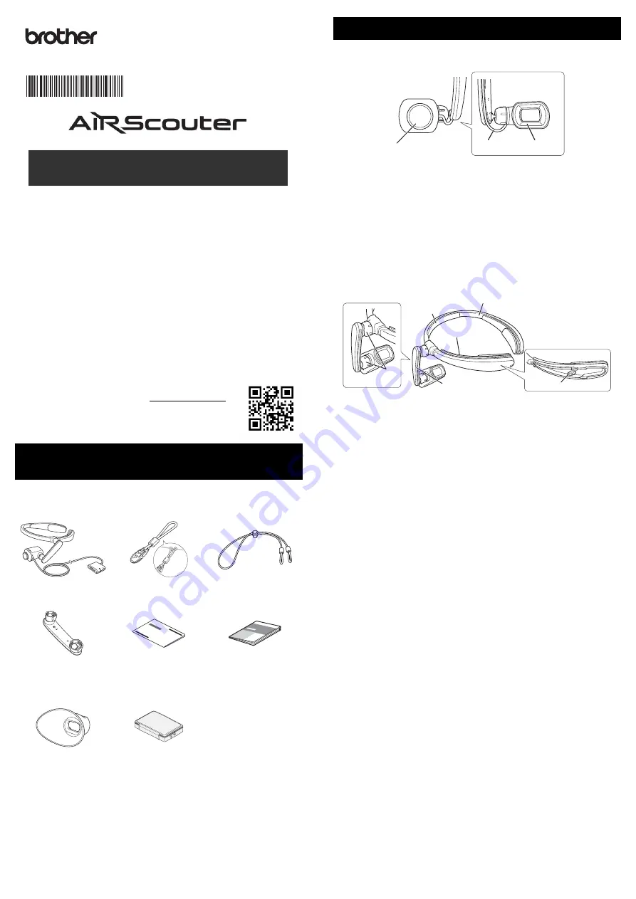
a

Focus Adjustment Dial

Adjusts the focus of the image on the head display by changing the 

focal length of the optics (from 30 cm to infinity).

b

Head Display Cable

Connects the head display to the control box and transmits power 

and video signals to the head display.

c

Eyecup

When attached, prevents the head display from touching the user’s 

eye.

a

Head Band

Attaches the AiRScouter to the user’s head and distributes the 

weight of the unit.

b

Forehead Pad 

Cushions the head band and prevents it from slipping down the 

user’s forehead.

c

Cable Channel

Holds the head display cable in place along the head band.

d

Rear Band Attachment Post

Allows the user to attach the rear band and tighten the head band 

around the head to prevent slippage.

e

Flexible Arm

Allows the user to adjust the position and angle of the head display 

relative to the eye.

f

Joint Dial

Loosens the ball joint to allow for adjustment of the flexible arm, or 

tightens it to fix the flexible arm's position and angle.

Unpack the machine and check the 

components

Head Display Unit

Cable Clip

*1

Rear Band

Flexible Arm 

(For Right Eye)

Quick Setup Guide 

(This Guide)

Product Safety Guide

Large Eyecup

Case

*2

English

WD-350B

Quick Setup Guide

Printed in Japan
D00UNN001A

Names and functions of key components

Head Display

Harness

c

a

b

b

a

f

e

d

c

Summary of Contents for AIRScouter WD-350B

Page 1: ...r receives a strong impact while in the case it may become damaged a Focus Adjustment Dial Adjusts the focus of the image on the head display by changing the focal length of the optics from 30 cm to infinity b Head Display Cable Connects the head display to the control box and transmits power and video signals to the head display c Eyecup When attached prevents the head display from touching the u...

Page 2: ...ol box 1 Before connecting an external battery to the control box ensure that the external battery has been fully charged For more information on charging a third party USB battery see the battery s manual 2 Connect the Micro USB B plug of a USB Type A to Micro USB B cable to the Micro USB B port of the control box 3 Connect the USB Type A plug to the USB Type A port of the external battery 4 Conn...

Page 3: ...s The focal length of the optics can be changed from 30 cm to infinity Rotation of the image The head display automatically adjusts the rotation of the image for example when switching the display from left eyed viewing to right eyed viewing to ensure that its orientation is correct To disable this function for example while performing a task that involves frequently changing the orientation of yo...

Page 4: ...ressing and holding the brightness button will change the zoom mode in the following order Normal Reduce Normal Attach the rear band 1 Press the area highlighted in the image below and slide the head band cover towards the end of the band to remove it 2 Slide the loop at one end of the rear band over the attachment post as shown in the illustration and feed the rear band through the opening at the...

Page 5: ... in the box to the head display by lining up the narrow end of the flexible arm with the threads on the head display and rotating the dial on the ball joint clockwise to tighten 8 Attach the flexible arm to the head band by lining up the wide end of the flexible arm with the threads on the head band and rotating the dial on the ball joint clockwise to tighten 9 Run the head display cable through t...

Page 6: ...g environment 1 Carefully remove the small eyecup from the head display as shown 2 Correctly align the large eyecup and then gently press the eyecup to attach it to the head display Important Be careful to avoid touching the lens while changing the eyecup You may dirty or damage the lens if you touch it Be careful to align and attach the eyecup correctly The eyecup or head display may be damaged i...

Page 7: ...pears to have dirt on it Is there dirt on the lens of the head display unit Clean the lens of the head display unit with a soft cloth If you are using a camera as an input device is there dirt on the lens of the camera Clean the lens of the camera The fit of the head band feels loose Are you using the rear band Use the rear band to tighten the head band Is the fit still loose when you are using th...

Reviews: