background image

15 


V. 1.2-14-03-17 

brookvent.co.uk 


www.brookvent.co.uk 


       T: +44 (0) 28 9061 6505 

4.13    FLOOR MOUNT 

The  aircycle  1.2 models 

AS 90-0102-FIN-01,  AS 90-0102-FIN-01V,  AS 90-0102-FINS-01, 

and


AS 90-0102-FINS-01V

 are designed for floor mounting only and comes complete with 

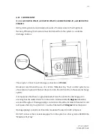
its mounting bracket already fitted. The unit should be attached to the Floor, as shown, 
mounted on a raised plinth. (Fig.1).  


Please ensure that this method of fixing is suitable for the mounting surface and that it 
can safely bear the load. 


Fig. 1 

349 

NB. Dry trap (Not 
Incl.)  must be fitted 
with a 10 degree fall. 

Summary of Contents for AS 90-0102-CIN-01

Page 1: ...at Summer Bypass Wall Mount AS 90 0102 CIN 01 aircycle 1 2 c w Integral Humidistat Ceiling Mount AS 90 0102 CINS 01 aircycle 1 2 c w Integral Humidistat Summer Bypass Ceiling Mount AS 90 0102 FIN 01 aircycle 1 2 c w Integral Humidistat Floor Mount AS 90 0102 FINS 01 aircycle 1 2 c w Integral Humidistat Summer Bypass Floor Mount Product codes above refer to standard system set up Add V to the end o...

Page 2: ...UCTIONS WITH THE PRODUCT Please read this manual fully prior to installing the MVHR unit 1 0 Introduction 2 2 0 Safety 4 3 0 Specifications Dimensions mm 6 4 0 Installation 11 5 0 Electrical Connections Wiring 20 6 0 Controls and Settings 22 7 0 Maintenance 27 8 0 User Operation 29 9 0 Trouble Shooting 31 ...

Page 3: ...ents with restricted space The system should be run continuously 24 hours a day and should only be disconnected by a competent person during service or maintenance Heat Recovery ventilation works best in new homes which are extremely airtight and have high efficiency ratings These dwellings require a high level of fresh air to ensure a healthy living environment The system works by drawing stale a...

Page 4: ...or a period of 5 years from date of purchase with the first year covering parts and labour and the remaining 4 years covering parts only In the instance of a defect Brookvent may repair the product replace the product free of charge or refund the cost of the product at Brookvent s own discretion In terms of installation operation and maintenance please follow all instructions provided If this prod...

Page 5: ...ry cloth only 2 2 Responsibility of the Installer Correct Installation balancing and commissioning of the MHRV unit Record measured air flow volumes on each of the valves at High and Low rate Compliance to requirements and local additional rules Explanation of the ventilation system to the user Warning for the user to check or replace the air filters on time All the above as set out in the latest ...

Page 6: ...y issues It is important that the filters are changed at least once per year or as required In new build properties it may be prudent to check change your filters after the first 3 months of occupancy depending on the amount of residual building dust present within the property Failure to do so will affect your warranty Filters can be purchased directly online from brookvent co uk ...

Page 7: ...rookvent co uk www brookvent co uk T 44 0 28 9061 6505 3 0 Specifications Dimensions 3 01 WALL MOUNT H 583mm x W 600mm x D 337mm 3 02 CEILING MOUNT L 670mm x W 600mm x D 349mm 3 03 FLOOR MOUNT L 670mm x W 600mm x D 349mm ...

Page 8: ...Duct Connections Standard Configuration Inverted Configuration Factory Set Must be specified at time of order Fresh from Outside Fresh to Home Extract to Outside Extract from House Outside Fresh from Outside Fresh to Home Extract to Outside Extract from House Outside FRONT FRONT ...

Page 9: ...ead Live Brown Neutral Black Earth Yellow Green 230v Switched Live Boost Grey Controls Independent fan speed control Trickle and boost settings for each fan Single 230v boost input Light switch humidistat PIR etc Boost over run timer adjustable between 0 15 min In built humidity sensor Boost activation Variable 60 100 RH factory set 70 Frost protection factory set at 5 degrees Celsius Tempering su...

Page 10: ...y Kitchen 1 Wet Room 100 Variable 0 53 93 Kitchen 2 Wet Room 100 Variable 0 57 91 Kitchen 3 Wet Room 100 Variable 0 67 90 Kitchen 4 Wet Room 100 Variable 0 82 89 Kitchen 5 Wet Room 100 Variable 0 97 88 Kitchen 6 Wet Room 100 Variable 1 16 87 Exhaust Terminal Configuration Fan Speed Setting Specific Fan Power W l s Heat Exchange Efficiency Kitchen 1 Wet Room 100 Variable 0 59 91 Kitchen 2 Wet Room ...

Page 11: ...tract Duct 29 10 31 7 29 7 47 3 40 33 3 28 22 2 41 34 Breakout 31 9 30 8 33 6 46 4 46 8 34 27 4 21 4 43 37 Speed 3 Open Supply Duct 38 18 33 8 40 8 56 7 55 8 51 7 42 6 30 3 56 46 24 Open Extract Duct 42 25 37 8 34 3 50 6 49 1 34 9 34 2 24 8 48 41 Breakout 42 16 28 7 33 3 50 3 46 2 40 4 33 8 25 4 48 41 Speed 4 Open Supply Duct 49 31 48 3 44 8 61 3 64 5 56 9 50 3 39 9 64 55 32 Open Extract Duct 53 4...

Page 12: ...alified electrician The MVHR unit is designed to be installed indoors within an attic storage cupboard or void space away from exposure to frost water or intense heat The system should be installed in a ventilated space A clear access space is required around the unit this will ensure ease of installation relating to ductwork wiring and the connection of the condensate drain It is important that f...

Page 13: ...the to the wall as shown using the wall bracket provided please ensure the mounting surface can safely bear the load of the unit using suitable screw fixings One bracket will be secured to the back of the unit as shown in Fig 1 the second bracket should be secured to the mounting surface as shown in Fig 2 Please ensure the brackets are level The unit can then be set onto the mounting surface with ...

Page 14: ... CIN 01V AS 90 0102 CINS 01 and AS 90 0102 CINS 01V are designed for ceiling mounting only The unit should be attached to the Ceiling as shown Fig 1 by first fixing the bracket to the unit using the fixings provided Fig 1 Fig 2 Fig 3 Brookvent supply drainage to this point Dry Trap Not Incl must be fitted with a 10 degree fall Trap not included ...

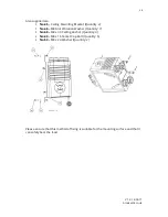
Page 15: ...ling Mounting Bracket Quantity 2 No 46 M8 Anti Vibration Washer Quantity 7 No 48 M8 x 30 Celling Anchor Quantity 4 No 49 M8 x 16 Socket Cap Bolt Quantity 6 No 50 M8 x 24 Washer Quantity 2 Please ensure that this method of fixing is suitable for the mounting surface and that it can safely bear the load ...

Page 16: ...90 0102 FINS 01V are designed for floor mounting only and comes complete with its mounting bracket already fitted The unit should be attached to the Floor as shown mounted on a raised plinth Fig 1 Please ensure that this method of fixing is suitable for the mounting surface and that it can safely bear the load Fig 1 349 NB Dry trap Not Incl must be fitted with a 10 degree fall ...

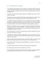
Page 17: ...ible Where it is not possible to continue throughout the dwelling in rigid 125mm diameter round pipe due to the void spaces available a conversion to rigid 204mm x 60mm flat rectangular ducting is recommended It is recommended that the number of bends in the ducting system is kept to a minimum Each of the external roof terminals wall terminals must be the equivalent to the open area of 125mm diame...

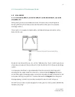
Page 18: ... Brookvent recommend the use of a 32mm Waterless Dry Trap on HRV systems as shown above to prevent the back flow of air into the HRV unit from the waste discharge system It is imperative that there is a gravitational fall from the unit to the discharge point ensuring that the water drains from the unit A minimum fall of 5 Degrees should be ensured throughout Drainage piping connections should be i...

Page 19: ...m Waterless Dry Trap on HRV systems as shown above to prevent the back flow of air into the HRV unit from the waste discharge system It is imperative that there is a gravitational fall from the unit to the discharge point ensuring that the water drains from the unit A minimum fall of 5 Degrees should be ensured throughout Drainage piping connections should be insulated if located in cold roof spac...

Page 20: ...Waterless Dry Trap on HRV systems as shown above to prevent the back flow of air into the HRV unit from the waste discharge system It is imperative that there is a gravitational fall from the unit to the discharge point ensuring that the water drains from the unit A minimum fall of 5 Degrees should be ensured throughout Drainage piping connections should be insulated if located in cold roof spaces...

Page 21: ...lator as to comply with current IEE wiring regulations A switch or circuit breaker must be used in the power supply circuit It should be in close proximity to the HRV unit and should be clearly marked as the disconnecting device for the HRV Unit Connecting to mains The aircycle 1 2 unit comes pre wired with 2m length of 4 core cable which should be connected into a fan isolation switch In turn a 3...

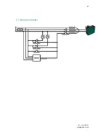
Page 22: ...21 V 1 2 14 03 17 brookvent co uk www brookvent co uk T 44 0 28 9061 6505 5 1 Wiring Schematic ...

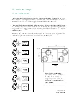
Page 23: ...y to day operation I e Trickle and an increased speed to be set I e Boost that operates only when the Grey switch wire is triggered by a 230v boost signal such as a Wall Switch or Passive Infrared Sensor If the Boost for either fan is required to be set it should always be set higher than the Trickle Turing these Speed Pots clockwise increases the fan speed Extract Trickle Extract Boost Supply Tri...

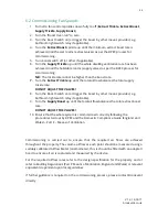
Page 24: ...pply trickle rate DO NOT ADJUST THE VALVES 8 Turn the Boost Switch on or trigger the boost by other means provided e g bathroom light switch relay if applicable 9 Turn the Supply Boost up until the total airflow balances the total extract boost rate DO NOT ADJUST THE VALVES 10 Ensure that the whole system is commissioned correctly following the procedures laid out by BPEC and the Domestic Complian...

Page 25: ...indles down Turn the boost switch on Turn the Extract boost spindle up until the extract boost rates are achieved kitchen 13l s bathroom 8l s En suite 8 l s Lock the valves in place Turn the boost switch off Turn the supply trickle spindle up to achieve the rates for the supply rooms living 11l s Dining 5l s Bedroom 8l s Lock the valves in place Turn the Extract up down until the whole dwelling ra...

Page 26: ...g is used to boost the system When a live 230v signal is applied by a switch or sensor the boost function will be triggered When the signal stops the boost will over run for a minimum of 15 mins as to ensure the system has adequately cleared the pollutants that were present This is also true for the internal humidistat feature in the aircycle 3 1 The 15min boost over run timer control is located o...

Page 27: ...ions via thermostatically responsive solenoid which operates on a linear scale between 20 Degrees Celsius No Summer Bypass and 27 Degrees Celsius Full Summer Bypass gradually increasing the amount of air directed around the Heat Recovery Core as the temperature of the extract air from the home rises thus comfortably regulating the indoor air temperature during warmer months This feature is factory...

Page 28: ...erform to the levels required 7 1 Filter Replacement The filters of this HRV unit will usually need to be changed every 6 12 months depending on occupancy use and the type of environment the dwelling is located in I e urban rural and their associated levels of airborne pollutants It is recommended that the filters are checked every 6 months Replacement filters can be purchased online at brookvent ...

Page 29: ...e following checks are also made when completing annual maintenance of the HRV unit Condensate Drain Ensure the condensation drain is firmly secured and is clear of any debris remove clean if necessary Fixings Ensure that all of the unit fixings and the mounting fixings have not become loose over time and are kept sufficiently tight ...

Page 30: ...the recovered heat and supplied into the habitable rooms such as bedrooms dining rooms and living rooms How your system is configured upon installation will influence how it can be operated at the user level Please ensure to refer to the commissioning certificate provided by your installer for full details General Guidance Your system may be set up to boost from trickle speed automatically via sen...

Page 31: ...These sensors detect humidity in the air and trigger the system into boost mode when humidity reaches a certain level These are typically placed in bathrooms or in kitchens Please note that the aircycle 1 2 system has an In built humidistat that operates in the same fashion Light switch The lighting circuit of the home can be used to boost the system meaning that when the occupier enters the room ...

Page 32: ...ooms and or kitchens When pressed it will trigger the system into boost mode for a defined time Trickle and Boost switch This is a simple on off switch with no determined time delay When the switch is flicked to boost the system goes into its boost state the switch then must be put back to trickle by the occupier for standard operation Please note that the aircycle 1 2 system has a minimum boost o...

Page 33: ... The system is constantly in Boost New houses can be quite damp with items drying out this can cause the inbuilt humidistat and external humidistats to activate The in built humidistat is disabled for the first hour after set up however if the system is boosting after this period the level can be adjusted to 100 effectively switching off the humidistat Remember to turn this stat down again after c...

Page 34: ...33 V 1 2 14 03 17 brookvent co uk www brookvent co uk T 44 0 28 9061 6505 Notes ...

Page 35: ...34 V 1 2 14 03 17 brookvent co uk www brookvent co uk T 44 0 28 9061 6505 Notes ...

Page 36: ... query you may have and we will be more than happy to assist you Brookvent Brook House Dunmurry Industrial Estate Dunmurry Belfast Northern Ireland BT17 9HU T 44 0 28 9061 6505 It is important to retain this manual and make a copy available to any person using or working with maintaining the system Brookvent operate a policy of continuous innovation and improvement and thus reserve the right to al...

Reviews: