20
bromic.com/heat
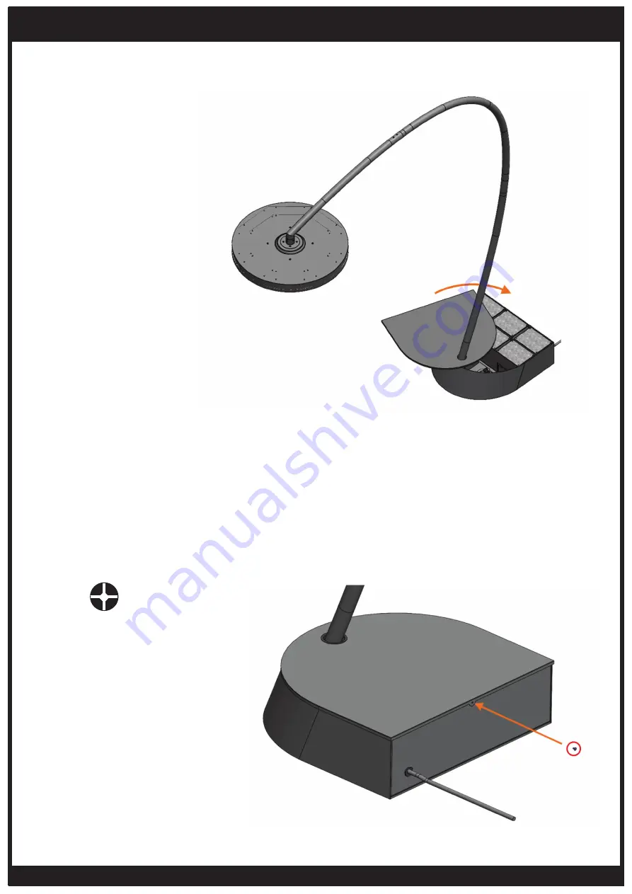
32. Fasten the Base Cover to the Base using the
Dome Head Screw (M4 - Length: 6mm).
HEATER INSTALLATION INSTRUCTIONS - PORTABLE
CONTINUED...
31. Rotate the Base Cover until it is in place
covering the Base.
1x
M4 - Length: 6mm
Page 1: ...VERSION 1 7 EU ECLIPSE SMART HEAT ELECTRIC PORTABLE 3400W BY BROMIC INSTRUCTION MANUAL WARNING PLEASE READ AND SAVE THESE INSTRUCTIONS FOR FUTURE REFERENCE ...
Page 2: ...ng READ THIS MANUAL CAREFULLY Read all instructions before installing servicing or using this heater Installation must comply with local building code This heater is hot when in use To avoid burns do not let bare skin touch the hot surfaces Keep combustible materials such as furniture pillows bedding papers clothes and curtains at least 1 metre from the heater head in all directions Improper insta...
Page 3: ...ELECTRICAL INSTALLATION 21 PORTABLE HEATER CONTROL WIRING DIAGRAM 22 OPERATION INSTRUCTIONS 23 26 REMOTE CONTROL FUNCTIONS 23 TURNING THE APPLIANCE ON 23 TURNING THE APPLIANCE OFF 23 PREPARING TO MOVE THE APPLIANCE 24 MOVING THE APPLIANCE 24 REMOTE CONTROL BATTERY 24 OPENING CONTROL BOX TO PAIR A NEW REMOTE 25 PAIRING REMOTE CONTROL TO HEATER PCB 25 PAIRING REMOTE CONTROL TO LED PCB 26 MAINTENANCE...
Page 4: ...ts For the Base and Arm please refer to the Maintenance and Servicing section for more details regarding troubleshooting and replacement parts The LED contained in this luminaire is non replaceable and must not be removed Do not perform maintenance until heater has been turned off power disconnected and heater temperature has cooled to room temperature Certain materials or items when stored under ...
Page 5: ...voted on the two assembled wheels When moving base ensure floor is adequately protected Heater must be installed on flat surface capable of withstanding at least 160kg Heater must not be installed on soft surfaces which cannot support the weight of heater e g grass mud dirt Do not lean on heater or rest any objects leaning up against heater including the arm Do not hang any foreign items off any p...
Page 6: ...in Australia New Zealand USA Canada Europe UK and are rated to IP54 for Ingress Protection making the Eclipse Smart HeatTM Electric Portable the perfect solution for a variety of indoor and outdoor heating applications PRODUCT FEATURES PRODUCT SPECIFICATIONS SPECIFICATIONS Model Eclipse Smart HeatTM Electric Portable 3400W Part No Portable Heater Head EU UK BH0820011 Part No Portable Arms EU UK BH...
Page 7: ...lastic vinyl siding canvas tri ply etc may subject to degradation at lower temperature It is the installer s responsibility to assure that adjacent materials are protected Heaters must be installed according to the minimum installation clearances shown in these diagrams Appliance must not be moved after installation causing the clearance distances to be reduced Dimensions shown in mm PORTABLE 2500...
Page 8: ...rm with Large O Ring fitted Instruction Manual This Document Box 2 Contents Lower Arm with Large O Ring fitted Contents Packed in 3 Boxes Box 1 Contents Eclipse Head Assembly with 4 5m cable plug Including pre assembled 4 x Dome Head Screws M4 Length 6mm 2 x Dome Head Screws M5 Length 14mm ...
Page 9: ...ed WARNING IMPORTANT This heater MUST be installed by an licensed electrical contractor Do not perform maintenance or carry out installation or assembly procedure while electrical power is switched on Wait 2 hours after switching off the heater before handling to prevent touching hot surfaces For longest product life and to maintain product appearance position heater under cover and protect from r...
Page 10: ... Cover to be uncovered 2 Remove the Dome Head Screw M4 Length 6mm which fastens the Base Cover to the rear of the Base and keep aside for later assembly Heavy Items 150 kg Maximum safe lifting 16kg per person Forklift must be used to move prior to breaking down crate WARNING For more information including video instructions please visit Bromic com heat 1x M4 Length 6mm Preassembled ...
Page 11: ...ove the Base Cover and place to the side on a non abrasive surface to avoid scratching 4 Remove 10 X 10 kg Base weights from the rear compartment of the Heater Base and place them nearby the desired heater location Heavy items 10 kg each Take caution when moving weights WARNING ...
Page 12: ... a flat surface in desired heater location 7 NOTE If installing in areas subject to high winds gusts or hurricanes heater base must be bolted down to ground using appropriately sized and type bolts not included suited for the ground surface through the 5 X Holes in the Heater Base Heavy Item Min Two Person Lift Maximum safe lifting 16 kg per person WARNING Fixing bolts not included ...
Page 13: ...he Base 9 Unwrap Lower Arm section from its packaging 10 Fit the Lower Arm section into base slotting the front two mounting holes on the bottom plate slot into the two M8 threads on the base dampeners WARNING Care should be taken when replacing weights into the base Gloves should be worn to protect hands and fingers from pinch hazards ...
Page 14: ...he dampeners using 2 X M8 Washers and 2X M8 Nuts 12 Fasten the rear two slots of the Lower Arm section to the Base using 2 X M8 Washers and 2X M8 Length 35mm bolts 13 Check that 1 X Large O ring 35mm ID is fitted on the connector section of the Lower Arm 2x 2x M8 Nut M8 Washer 2x 2x M8 Bolt Length 35mm M8 Washer Ensure all Nuts Washers and Bolts are fully assembled and tightened to ensure arm rema...
Page 15: ...ion to the Heater Head using the 2 X Dome Head Screws M5 Length 14mm preassembled to head Line up the screw marked A on the heater head with the screw hole marked A on the top arm section and respectively B with B Both screws should be fully inserted into the two screw holes perpendicular to the arm so that the bromic logo on the glass is at the front of the heater Note Extra screw holes are provi...
Page 16: ...section from packaging 21 Check that 1 X Large O ring 35mm ID is fitted to the connector section of the Middle Arm 2x M4 Length 6mm Both 2x screws must be assembled to ensure arm remains assembled IMPORTANT 19 Fasten the 4 X Dome Head Screws M4 Length 6mm to the head to lock the angle of the Heater Head relative to the Top Arm section NOTE These screws will be used later to adjust the head angle o...
Page 17: ...Head cable through the Lower Arm and pull through the cable slack into the base Two person lift Maximum safe lifting 16 kg per person 25 Fasten the Middle Arm to the Lower Arm using 2 x Slotted Head Screws M4 Length 6mm with O Rings fitted WARNING 2x M4 Length 6mm Both 2x screws must be assembled to ensure arm remains assembled IMPORTANT ...
Page 18: ...ng the 4 x Dome Head screws M4 Length 6mm on the heater head NOTE If heater head can not be made level by adjusting 4 screws check mounting floor provides a level surface to support the heater on All 4 x Dome Head screws must be tightened completely once heater head is level to the ground to prevent head from moving The base MUST NOT be plugged into power source when attaching the connector DANGER...
Page 19: ...NUED 29 Attach the rubber cable grommet around the cable and place it in the square slot in the connector box ensuring the flat face is facing upwards FLAT FACE TOP 30 Fasten the Small Connector Box lid using the 4 X Oval Head Screws 4 40 Length 3 8 4x 4 40 Length 3 8 ...
Page 20: ... heat 32 Fasten the Base Cover to the Base using the Dome Head Screw M4 Length 6mm HEATER INSTALLATION INSTRUCTIONS PORTABLE CONTINUED 31 Rotate the Base Cover until it is in place covering the Base 1x M4 Length 6mm ...
Page 21: ... connected to a properly grounded electrical source Isolate mains before installing Use only with a properly secured heater Check product label for correct voltage and wattage to ensure power source conforms to the heater s requirements Make all connections in accordance with local electrical code regulations For outdoor installation all connections must be made in accordance with local electrical...
Page 22: ...or re pairing remote to Heater control PCB Button for re pairing remote to LED PCB Power supply 220 240V a c Minimum Circuit Ampacity 17A Supplied with heater base Small connector box supplied with heater base 6 core connector Power cable from heater supplied with heater head TRANSFORMER MEANWELL LPF 25 24 HEATER CONTROL PCB EMI FILTER YB22D1 3A W LED PCB DIMMER DC OUT 24V WHITE 24V DC RED 24V DC ...
Page 23: ...t at 50 of total 5 To Lower lights Press Hold OFF DIM until the lights have lowered to the desired level 6 To Brighten lights Press Hold 100 DIM until the lights have increased to the desired level NOTE It is normal to observe a small dim spot on the LED at the location where the LED joins together TURNING THE APPLIANCE OFF 1 Using the Remote Control press on the desired Heater setting Heater OFF ...
Page 24: ... way PREPARING TO MOVE THE APPLIANCE 1 Unplug the supply lead of the appliance from the wall outlet 2 Remove 1x M4x6mm Screw from Base Top Cover and rotate the Base Top Cover to expose the Base weights and any floor fastening bolts 2 Remove any floor fastening bolts from inside the base 3 Ensure a clear path is available from where the appliance is located and where it is to be moved to MOVING THE...
Page 25: ...Cover Heater 100 Heater output at full 100 Heater 66 Heater output at 66 of total Heater 33 Heater output at 33 of total Heater OFF Heater off Lights 100 DIM Lights output at full 100 or HOLD to DIM Up Lights 50 Light output at 50 of total Lights OFF DIM Light off or HOLD to DIM Down DANGER ELECTRICAL SHOCK HAZARD Serious injury or death may occur Do not touch any components other than specified b...
Page 26: ...paired 5 Refit the lid to the Portable Control Box using the 6x Oval head screws 4 40 Length 1 2 6 Refit the Portable Control Box Cover using 4x M4x8mm Dome Head Phillips screws 7 Replace the two weights onto the Portable Control Box Cover and rotate the Base Top Cover to the correct position on the Base 8 Replace the 1x M4x6mm Dome Head Screw into the rear of the Base Top Cover Heater 100 Heater ...
Page 27: ...d For longest product life and to maintain product appearance mount heater under cover and protect from rain and weather whenever possible The exterior housing of the heater should be cleaned regularly To clean the appliance ensure heater is off and has been off for at least 2 hours after operation before wiping off any dirt dust with a soft damp cloth glass cleaner Salt in the air can cause rusti...
Page 28: ...ed or faulty control 1 Choose lighting setting using remote 50 or 100 DIM 2 Connect to 220 240V power supply 3 Check connection to power supply 4 Change remote batteries 5 Move remote closer to heater 6 Move remote closer to heater disable other radio emitting devices 7 Pair remote to LED PCB Not enough Light 1 Incorrect lighting setting chosen 2 Light too small for application 1 Choose higher lig...