


NOTE
New WWN cards are shipped preinstalled in the replacement chassis. Do not replace the WWN cards in the replacement
chassis with the old WWN cards from chassis that you are replacing. This will result in licensing and return materials
authorization (RMA) issues for your product. The original license will be transferred to the replacement chassis, based on the
license identification (LID) of the new, preinstalled WWN card, through the RMA process. You should be provided a license for
the new chassis through email. If you have not received this, contact your Brocade support representative.
DANGER
For safety reasons, the ESD wrist strap should contain a series 1 megaohm resistor.
1. Record the chassis serial number, SKU, and WWN printed on the chassis label. This label is located on the upper portion of the
chassis to the left of the fan assemblies on the nonport side.
You may need this information to transfer licenses to the new chassis.
2. Replace the fan assemblies (
3. Replace the power supplies or filler panels (
4. Replace the control processor (CP) blades (
on page 156).
5. Replace the core routing (CR) blades (
6. Replace the port and extension blades or filler panels (
7. Replace the cable management finger assemblies.
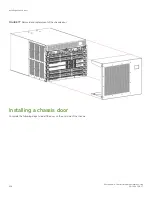
8. Replace the chassis door. The door is required to meet EMI compliance. Refer to
on page 206.
9. Plug in power cords from power source into all installed power supplies to power on device. Refer to
on page 66.
The device performs a power-on self-test (POST). The POST takes a minimum of three minutes and is complete when LED
activity returns to the standard state. The power supply LED will light green when power is applied. Note that after one power
supply is plugged into AC power, LEDs on the remaining installed power supplies will flash green until they also have full power.
10. Verify that the device is powered on and POST is complete (all power LED indicators on the blades should be a steady green).
11. Verify that all components are functioning correctly by checking their LEDs. If the LEDs do not indicate correct operation, try
reinstalling the corresponding component.
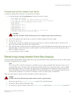
Synchronizing airflow direction on WWN cards
An airflow direction mismatch may occur if the airflow direction, nonport-side intake (NPI) or nonport-side exhaust (NPE), for installed fan
and power supply assembly FRUs does not match airflow direction set on new WWN cards shipped with replacement chassis.
You can check airflow direction for fans in fan and power supply assemblies installed in device with airflow direction set on WWN cards
by entering the
chassisShow
command. Airflow direction of fans and power supplies displays as "Fan Direction" under each fan or power
supply unit. System airflow direction displays as "System Airflow" under the WWN card unit.
If the chassisShow command or RASlog messages indicate a mismatch between system airflow direction and airflow direction of fan in
power supply or fan assemblies refer, to
Configuring airflow direction on WWN cards
on page 177 for instructions on configuring correct
airflow direction on WWN cards.
Synchronizing airflow direction on WWN cards
Brocade X6-4 Director Hardware Installation Guide
53-1004106-07
219
Summary of Contents for X6-4
Page 12: ...Brocade X6 4 Director Hardware Installation Guide 12 53 1004106 07...
Page 20: ...Brocade X6 4 Director Hardware Installation Guide 20 53 1004106 07...
Page 28: ...Brocade X6 4 Director Hardware Installation Guide 28 53 1004106 07...
Page 64: ...Brocade X6 4 Director Hardware Installation Guide 64 53 1004106 07...
Page 86: ...Brocade X6 4 Director Hardware Installation Guide 86 53 1004106 07...
Page 102: ...Brocade X6 4 Director Hardware Installation Guide 102 53 1004106 07...
Page 130: ...Brocade X6 4 Director Hardware Installation Guide 130 53 1004106 07...
Page 140: ...Brocade X6 4 Director Hardware Installation Guide 140 53 1004106 07...
Page 166: ...Brocade X6 4 Director Hardware Installation Guide 166 53 1004106 07...
Page 196: ...Brocade X6 4 Director Hardware Installation Guide 196 53 1004106 07...
Page 200: ...Brocade X6 4 Director Hardware Installation Guide 200 53 1004106 07...
Page 204: ...Brocade X6 4 Director Hardware Installation Guide 204 53 1004106 07...
Page 210: ...Brocade X6 4 Director Hardware Installation Guide 210 53 1004106 07...
Page 224: ...Brocade X6 4 Director Hardware Installation Guide 224 53 1004106 07...
Page 238: ...Brocade X6 4 Director Hardware Installation Guide 238 53 1004106 07...