


TABLE 12
Configuration and verification tasks (continued)
Task
Task details or additional information
Verify installed licenses and license key
Enter the
licenseShow
command to determine display enabled licenses and the
license key.
Enter the
licenseIdShow
command to obtain the chassis ID.
Record the license key and chassis ID for future reference.
Verify correct operation of director.
Check LEDs on blades and FRUs, and use the following commands to verify
operation:
•
psShow
•
fanShow
•
switchShow
•
fabricShow
•
slotShow
•
tempShow
•
historyShow
•
errdump
Back up the configuration.
Use the
configUpload
command.
Items required
The following items are required for initial setup and verification of the device:
•
The device, mounted and installed with the required blades, FRUs, transceivers, and cables and is connected to a power source.
•
A workstation computer with an installed terminal emulator application, such as HyperTerminal for Windows.
•
An unused IP address with corresponding subnet mask and gateway address.
•
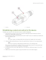
A serial cable (provided) with an RJ-45 connector.
•
An RJ-45 to DB-9 adapter.
•
Three Ethernet cables (including one spare).
•
Access to an FTP server or USB device for backing up (uploading) or downloading the device configuration or collecting
supportsave
output data (optional).
•
A Brocade USB drive for collecting
supportsave
output data (optional)
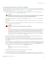
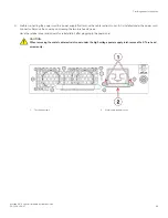
Providing power to the device
Perform the steps to provide power that are applicable to your power supply model. Observe the following for all power connections:
•
Before connecting power, refer the following.
–
Electrical caution and danger statements in
on page 23
–
Power supply specifications section in the
Brocade X6 Directors Technical Specifications
on page 225 for power supply
requirements of your device.
•
Connect each power supply to a different power source or circuit to provide full redundancy.
•
Route the power cords so they will be out of the way when connected to the power source. Ensure that the power cords have a
minimum service loop of 15.2 cm (6 in.) and are routed to avoid stress.
•
Remember that power is supplied to the device as soon as the first power supply is connected to a power source.
Items required
Brocade X6-4 Director Hardware Installation Guide
66
53-1004106-07
Summary of Contents for X6-4
Page 12: ...Brocade X6 4 Director Hardware Installation Guide 12 53 1004106 07...
Page 20: ...Brocade X6 4 Director Hardware Installation Guide 20 53 1004106 07...
Page 28: ...Brocade X6 4 Director Hardware Installation Guide 28 53 1004106 07...
Page 64: ...Brocade X6 4 Director Hardware Installation Guide 64 53 1004106 07...
Page 86: ...Brocade X6 4 Director Hardware Installation Guide 86 53 1004106 07...
Page 102: ...Brocade X6 4 Director Hardware Installation Guide 102 53 1004106 07...
Page 130: ...Brocade X6 4 Director Hardware Installation Guide 130 53 1004106 07...
Page 140: ...Brocade X6 4 Director Hardware Installation Guide 140 53 1004106 07...
Page 166: ...Brocade X6 4 Director Hardware Installation Guide 166 53 1004106 07...
Page 196: ...Brocade X6 4 Director Hardware Installation Guide 196 53 1004106 07...
Page 200: ...Brocade X6 4 Director Hardware Installation Guide 200 53 1004106 07...
Page 204: ...Brocade X6 4 Director Hardware Installation Guide 204 53 1004106 07...
Page 210: ...Brocade X6 4 Director Hardware Installation Guide 210 53 1004106 07...
Page 224: ...Brocade X6 4 Director Hardware Installation Guide 224 53 1004106 07...
Page 238: ...Brocade X6 4 Director Hardware Installation Guide 238 53 1004106 07...