
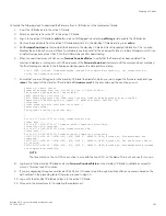


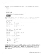


9. Verify the new card settings by running the following commands and comparing the output with the original
supportsave
data:
•
licenseidshow
•
ipaddrshow
•
switchname
•
chassisname
•
wwncardshow ipdata
•
chassisshow
(look at the WWN and Chassis information at the bottom)
10. If replacing the second WWN card, repeat the previous steps in this procedure for the other card.
11. Install the WWN bezel on the chassis.
a)
Orient the bezel on the chassis.
b) Insert and tighten both screws using a Phillips screwdriver.
12. Pack faulty WWN cards in the packaging provided with the replacement cards, and return them to Brocade Support for failure
analysis (FA).
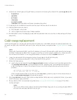
Cold-swap replacement
Use this procedure When you can interrupt system operation and replace one or both WWN cards with the system powered down. You
can replace one WWN card or both WWN cards, one at a time, with system power on using steps under
on page
173.
NOTE
Be aware that if replacing both WWN cards, the IP addresses on the new WWN cards will be in effect when the device powers
up. If these IP addresses are different from the previous cards, then you will not be able to establish ssh or other sessions that
use the previous IP addresses. You can change IP addresses on the new cards using the
ipaddrset
command.
1. Unpack the replacement WWN card assembly and save the packaging for the faulty WWN card(s).
The WWN card assemblies are labeled #1 for the left slot and #2 for the right slot.
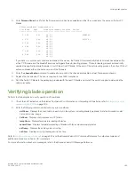
2. Perform the following steps.
a)
Log in to the device and execute the
switchcfgpersistentdisable
command on the main switch and other logical switches.
The
switchcfgpersistentdisable
command disables the switches, and ensures they remain disabled after the power is
cycled. This allows you to check all the settings so that you can verify the settings before placing the device back into
production.
switch:admin> switchcfgpersistentdisable
Switch's persistent state set to 'disabled'
If there are other logical switches on your chassis, use the
setcontext
command to connect to all the other switches and
then run
switchcfgpersistentdisable
on these switches as well.
3. Enter the
sysShutdown
command. When command output indicates that the device has completed shut-down, remove power
cords from all power supply assemblies.
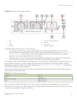
4. Remove defective WWN card assemblies using steps under
Removing the WWN card and bezel
on page 176, and then
continue with step 5.
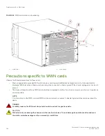
NOTE
There are two WWN card assemblies located behind the WWN bezel (logo plate). As you are facing the bezel, WWN 1
is located on the left side, and WWN 2 is on the right.
Cold-swap replacement
Brocade X6-4 Director Hardware Installation Guide
174
53-1004106-07
Summary of Contents for X6-4
Page 12: ...Brocade X6 4 Director Hardware Installation Guide 12 53 1004106 07...
Page 20: ...Brocade X6 4 Director Hardware Installation Guide 20 53 1004106 07...
Page 28: ...Brocade X6 4 Director Hardware Installation Guide 28 53 1004106 07...
Page 64: ...Brocade X6 4 Director Hardware Installation Guide 64 53 1004106 07...
Page 86: ...Brocade X6 4 Director Hardware Installation Guide 86 53 1004106 07...
Page 102: ...Brocade X6 4 Director Hardware Installation Guide 102 53 1004106 07...
Page 130: ...Brocade X6 4 Director Hardware Installation Guide 130 53 1004106 07...
Page 140: ...Brocade X6 4 Director Hardware Installation Guide 140 53 1004106 07...
Page 166: ...Brocade X6 4 Director Hardware Installation Guide 166 53 1004106 07...
Page 196: ...Brocade X6 4 Director Hardware Installation Guide 196 53 1004106 07...
Page 200: ...Brocade X6 4 Director Hardware Installation Guide 200 53 1004106 07...
Page 204: ...Brocade X6 4 Director Hardware Installation Guide 204 53 1004106 07...
Page 210: ...Brocade X6 4 Director Hardware Installation Guide 210 53 1004106 07...
Page 224: ...Brocade X6 4 Director Hardware Installation Guide 224 53 1004106 07...
Page 238: ...Brocade X6 4 Director Hardware Installation Guide 238 53 1004106 07...