


Time and items required
The replacement procedure for the core switch blade takes approximately 30 minutes. The following items are required for the core
switch blade replacement:
•
Electrostatic discharge (ESD) grounding strap
•
Workstation computer
•
Replacement blade or filler panel
•
#1 Phillips screwdriver
•
QSFP transceivers (as needed)
•
Optical cables (as needed)
NOTE
For information about the transceivers that are qualified for this Brocade device, refer to the "Installing Transceivers and Cables"
section.
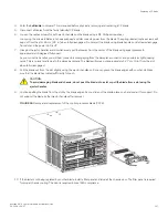
Replacing a core routing blade
Use the following procedures in this section to replace routing blades.
•
on page 146. Use these procedures to ensure that traffic is not disrupted through existing ICL
connections when you are replacing a core routing blade. If ICLs are not connected to the blade or traffic through ICL ports has
ceased, you can skip these procedures and go to
•
on page 147. Use these procedures to remove a blade from the chassis.
•
Installing a core routing blade
on page 148. Use these procedures to install a blade into an empty chassis slot.
NOTE
Perform these procedures to remove and install one core routing blade at a time while chassis power is on. You must replace a
blade and ensure its operation before replacing the other core routing blade. Removing both blades will shut down the chassis.
To replace both blades at the same time, power off the chassis and follow steps under
Installing a core routing blade
on page 148.
Preparing for replacement
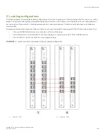
For nondisruptive replacement of a core blade, ensure that the core blade in the system that you are not replacing is active and is allowing
traffic through ICL ports to the same fabrics as ICL ports on the blade being replaced.
Use the following procedures to ensure that traffic will offload from the blade that you are replacing to the other core blade in the system
during replacement. This ensures nondisruptive impact on existing traffic flowing through the blade's ICLs. If ICLs are not connected to
the blade or traffic over blade ICLs has been halted, skip these procedures and go on to
on page 147.
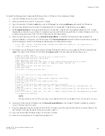
1. Ensure that Lossless Dynamic Load Sharing is enabled on each logical switch that resides on each physical switch that has ICL
connections through the core blades. Log into each logical switch using an account with admin permissions, and then enter
dlsShow
.
"DLS is set with Lossless enabled" should display if Lossless is enabled.
Time and items required
Brocade X6-4 Director Hardware Installation Guide
146
53-1004106-07
Summary of Contents for X6-4
Page 12: ...Brocade X6 4 Director Hardware Installation Guide 12 53 1004106 07...
Page 20: ...Brocade X6 4 Director Hardware Installation Guide 20 53 1004106 07...
Page 28: ...Brocade X6 4 Director Hardware Installation Guide 28 53 1004106 07...
Page 64: ...Brocade X6 4 Director Hardware Installation Guide 64 53 1004106 07...
Page 86: ...Brocade X6 4 Director Hardware Installation Guide 86 53 1004106 07...
Page 102: ...Brocade X6 4 Director Hardware Installation Guide 102 53 1004106 07...
Page 130: ...Brocade X6 4 Director Hardware Installation Guide 130 53 1004106 07...
Page 140: ...Brocade X6 4 Director Hardware Installation Guide 140 53 1004106 07...
Page 166: ...Brocade X6 4 Director Hardware Installation Guide 166 53 1004106 07...
Page 196: ...Brocade X6 4 Director Hardware Installation Guide 196 53 1004106 07...
Page 200: ...Brocade X6 4 Director Hardware Installation Guide 200 53 1004106 07...
Page 204: ...Brocade X6 4 Director Hardware Installation Guide 204 53 1004106 07...
Page 210: ...Brocade X6 4 Director Hardware Installation Guide 210 53 1004106 07...
Page 224: ...Brocade X6 4 Director Hardware Installation Guide 224 53 1004106 07...
Page 238: ...Brocade X6 4 Director Hardware Installation Guide 238 53 1004106 07...