22
Brocade FastIron X Series Chassis Hardware Installation Guide
53-1001723-02
Hardware features
1
Console port
The Console port on the management module is a standard DB-9 serial connector through which
you can attach a PC or terminal to configure the system using the command line interface (CLI).
The Console port interfaces the control plane only and not the data plane.
Reset button
The reset button on the management module allows you to restart the system. The reset button is
recessed to prevent it from being pushed accidentally.
The reset button is located next to the console port on the management module.
Switch fabric modules (
FSX 800
and
FSX 1600
only)
The switch fabric modules switch user packets from one interface module installed in the chassis
to another. Unlike the FSX, which has a switch fabric module built into the management module,
the switch fabric modules in the
FSX 800
and
FSX 1600
chassis are separate from the
management modules and are physically located next to the management modules.
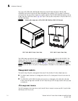
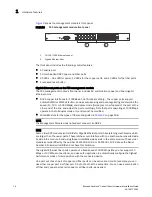
shows the
FSX 800
and
FSX 1600
switch fabric module.
FIGURE 14
FSX 800
and
FSX 1600
switch fabric module
Act
Right-most LED above the port.
On or Blinking
The port is transmitting and receiving
traffic.
Off
The port is not transmitting or receiving
traffic.
1000 Mbps Fiber Port LEDs
Lnk or Act
Round LED located beneath the
fiber connectors
On (Green)
A link is established with the remote port.
Blinking
The port is transmitting and receiving
packets.
Off
A link is not established with the remote
port.
10-GbE Port LEDs
Lnk
Top-most LED to the left of the port. On
Fiber port is connected.
Off
No fiber port connection exists.
Act
Bottom-most LED to the left of the
port.
On or Blinking
The port is transmitting and receiving
traffic.
Off
The port is not transmitting or receiving
traffic.
TABLE 7
FSX 800
and
FSX 1600
management module LEDs (Continued)
LED
Description and Position
State
Meaning
Pwr
Active


