2.1.2 Power Supply
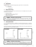
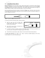
The 415/240V power supply requirements for this machine are of a high level and unauthorised interference and
or inadequate maintenance could result in a situation that could put the operator at risk. A
qualified
electrical
engineer should be assigned to maintain and repair the system.
2.2
General Requirements
Lighting
Insufficient lighting during the operation of the drill unit would constitute a safety hazard for the people concerned.
For this reason, the user of the machine must provide adequate lighting in the working area to eliminate areas in
shadow, whilst also preventing dazzling illumination sources (reference standard
ISO 8995 - 2002
‘Lighting of
Indoor Workplaces
’
).
Connections
Check that the power supply cables, compressed air supply and/or coolant system complies with, and are
operating within the acceptable range of the drill capabilities.
Faulty, damaged or worn components must be
replaced immediately.
Earthing Systems
The installation of the earthing system must comply with the requirements stated in the
IEC Standards Part 195:
Earthing and Protection Against Electric Shocks 1998.
2.3
Advice for the Operator
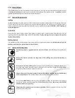
Protective eyewear or goggles must be worn at all times
while attending and operating the
drill.
Ensure that hands and arms are kept clear of the drilling zone when the machine is
operating.
Do not wear oversize clothing
with long sleeves and oversize gloves, bracelets, necklaces or
any other loose object that may become entangled in the machine’s tooling bit during drilling.
Long hair must be tied back or placed in a hair net.
Always disconnect the power supply to the machine before carrying out any maintenance
work or adjustments
. This includes cases of abnormal operations of the machine.
The operator
MUST NOT
conduct any risky operations or those not required for the drilling in
course (eg. remove swarf shavings from the machine while drilling).
Never move the 3M drill
while the machine is operating
.
Always keep the workplace area as clean as possible
. Remove equipment, tools or any other
objects from the drilling zone.
5
Summary of Contents for 3M
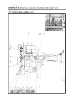
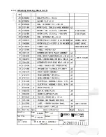
Page 12: ...CHAPTER 4 Drawings Layouts Assembly and Spare Parts 4 1 1 Assembly Drawing Sheet 1 of 5 9 ...
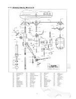
Page 13: ...4 1 2 Assembly Drawing Sheet 2 of 5 10 ...
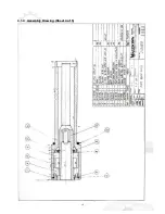
Page 14: ...4 1 3 Assembly Drawing Sheet 3 of 5 11 ...
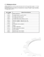
Page 15: ...4 1 4 Assembly Drawing Sheet 4 of 5 12 ...
Page 17: ...4 2 Switch Assembly 14 ...

