background image

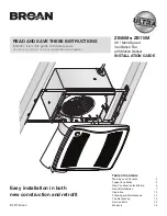
ZB80M 

n

 ZB110M  Installation Guide

Page 2

WARNING

TO REDUCE THE RISK OF FIRE, ELECTRIC SHOCK, OR 

INJURY TO PERSONS, OBSERVE THE FOLLOWING: 

1.  Use this unit only in the manner intended by the manufacturer. 

If you have questions, contact the manufacturer at the address 

or telephone number listed in the warranty.

2.  Before servicing or cleaning unit, switch power off at service 

panel and lock the service disconnecting means to prevent 

power from being switched on accidentally. When the service 

disconnecting means cannot be locked, securely fasten a 

prominent warning device, such as a tag, to the service panel.

3. Installation work and electrical wiring must be done by a 

qualified person(s) in accordance with all applicable codes 

and standards, including fire-rated construction codes and 

standards.

4.  Sufficient air is needed for proper combustion and exhausting 

of gases through the flue (chimney) of fuel burning equipment 

to prevent backdrafting. Follow the heating equipment 

manufacturer’s guideline and safety standards such as those 

published by the National Fire Protection Association (NFPA), 

and the American Society for Heating, Refrigeration and 

Air Conditioning Engineers (ASHRAE), and the local code 

authorities.

5. When cutting or drilling into wall or ceiling, do not damage 

electrical wiring and other hidden utilities.

6.  Ducted fans must always be vented to the outdoors.
7.  Use only ON/OFF switch, mechanical timer or relay-switched 

control.

8.  Acceptable for use over a tub or shower when connected to 

a GFCI (Ground Fault Circuit Interrupter) - protected branch 

circuit.

9.  This unit must be grounded.

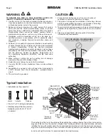
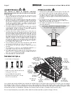
Typical Installation

CAUTION

1

.  For general ventilating use only. Do not use to exhaust 

hazardous or explosive materials and vapors.

2.  This product is designed for installation in flat ceilings. Sensor 

will not function reliably if product is not installed in flat ceiling. 

DO NOT MOUNT THIS PRODUCT IN A WALL.

3.  To avoid motor bearing damage and noisy and/or unbalanced  

impellers, keep drywall spray, construction dust, etc. off power 

unit.

4.  Please read specification label on product for further 

information and requirements.

45°

45°

•  Installation is the same for:

•  Fits in 2" x 8" ceiling construction.
•  Infinitely adjust the fan position 

between joists from 14" to 24"  
on center.

*Purchase

separately.

INSULATION* 

(Place around and 

over Fan Housing.)

ROOF CAP*

(with built-in

damper)

FAN

HOUSING

POWER

CABLE*

ROUND

DUCT*

ROUND

ELBOWS*

Seal gaps

around

Housing.

Seal duct

joints with

tape.

OR

Keep duct

runs short.

   WALL CAP* 

(with built-in

damper)

NOT FOR USE IN A COOKING AREA

 Do not install above or inside this area

Floor

Cooking
Equipment

Joists    I-Joists          Trusses

The ducting from this fan to the outside of the building has a strong effect on the air flow, noise and en-

ergy use of the fan. Use the shortest, straighest duct routing possible for best performance, and avoid 

installing the fan with smaller ducts than recommended. Insulation around the ducts can reduce en-

ergy loss and inhibit mold growth. Fans installed with existing ducts may not achieve their rated airflow.

6-inch round rigid metal duct is recommended for best performance.

Summary of Contents for ZB110M

Page 1: ...with homeowner Register your product online at www broan com register Easy installation in both new construction and retrofit Table of Contents Warnings and Cautions 2 Typical Installation 2 New Construction Installation 3 Retrofit Installation 7 Operation 12 Cleaning and Maintenance 12 Troubleshooting 12 Service Parts 13 Warranty 14 2017 Broan ...

Page 2: ...for use over a tub or shower when connected to a GFCI Ground Fault Circuit Interrupter protected branch circuit 9 This unit must be grounded Typical Installation CAUTION 1 For general ventilating use only Do not use to exhaust hazardous or explosive materials and vapors 2 This product is designed for installation in flat ceilings Sensor will not function reliably if product is not installed in fla...

Page 3: ...als needed 6 round metal ducting recommended for best performance Use of other ducting is acceptable but may impact performance Roof cap or wall cap built in damper recommended Tape to seal duct connections Electrical wiring and supplies per local code requirements 1 Remove Packaging 2 Install Mounting Frame Parts Bag holds Knockout Plate and six 6 screws Remove Instruction Sheet Punch out Mask fr...

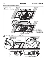
Page 4: ...r and Ducting Position Housing between joists and crimp channel on both sides of Mounting Frame to lock Housing in place Do not crimp Housing Screws from Parts Bag Top and bottom flanges go outside Housing Insert tab into slot inside Housing Screw from Parts Bag 6 to 4 Reducer for Model ZB80M only Tape Tape Tape 6 Ducting 4 Ducting snap ...

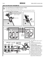
Page 5: ...TIONS ARE USED SENSOR CONTROL RED MASTER ON OFF SWITCH MANUAL ON SWITCH KNOCKOUT PLATE RECEPTACLES 120 VAC LINE IN SWITCH BOX BLACK WHITE RED BLUE purchase separately SENSOR CONTROL SWITCH GROUND green or bare ORANGE BROWN See OPERATION section on page 12 for details MASTER switch turns fan system on and shuts it off for fan cleaning and maintenance purposes SENSOR CONTROL switch turns motion cont...

Page 6: ...eaning and Maintenance and Troubleshooting Mask protects unit during construction Remove before installing Grille Install ceiling material Cut out around Housing Plug in Sensor CAUTION If the blower was unplugged power must be disconnected see page 2 WARNING item 2 before inserting motor plugs into control assembly IN ORDER TO PREVENT MOTOR CONTROL DAMAGE ...

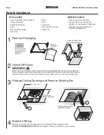
Page 7: ...existing wiring to make sure it is not damaged If any damage is found DO NOT CONTINUE INSTALLATION of this product Contact a qualified person s for repair Remove Instruction Sheet Punch out Mask from packaging See Step 12 1 Remove Packaging 2 Switch Off Power 4 Examine Wiring 3 Enlarge Ceiling Opening and Remove Existing Fan Ruler Pencil Drywall saw Claw hammer or pry bar Utility knife Materials n...

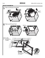
Page 8: ... 4 5 1 1 2 3 3 Retrofit Installation 5 Remove Blower Assembly 6 Remove Wiring Panel 7 Insert Mounting Frame Both sides Set aside Blower Assembly Set aside Wiring Panel Set aside screw Bend up four tabs Remove screws from Mounting Frame and set aside ...

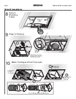
Page 9: ...de in Step 7 Pull existing wiring into Housing as it is inserted into Mounting Frame Pull existing ductwork into Housing Insert tab into slot inside Housing 10 Attach Ducting and Duct Connector 8 Secure Mounting Frame 9 Snap in Housing snap 6 to 4 Reducer for Model ZB80M only Tape Tape Tape 6 Ducting 4 Ducting ...

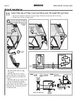
Page 10: ... wiring diagram FAN SENSOR CONTROL BLK WHT BLK ORG MASTER WALL SWITCH GRD WHT BLK GRD WHT BLK BRN 120 VAC LINE IN 14 2 RED MASTER WALL SWITCH KNOCKOUT PLATE RECEPTACLES 120 VAC LINE IN SWITCH BOX BLACK WHITE purchase separately GROUND green or bare ORANGE BROWN See OPERATION section on page 12 for details MASTER switch turns fan system on along with motion control and shuts them off for cleaning a...

Page 11: ...s are needed place Mask in Housing after Blower Assembly is secured See New Construction Installation Step 6 Remove Mask before installing Grille Screws from Parts Bag Plug in Sensor CAUTION Power must be disconnected see page 2 WARNING item 2 before inserting motor plugs into control assembly IN ORDER TO PREVENT MOTOR CONTROL DAMAGE 1 2 3 1 2 ...

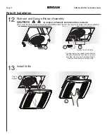
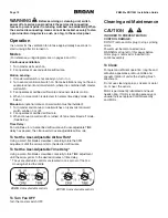
Page 12: ...e 3 When manual on wall switch is turned off fan enters timed off mode See below Time Delay Fan continues to run at cerified airflow rate until user adjustable TIME delay has passed then fan reverts to user adjustable airflow rate To Set the User Adjustable Airflow Rate Using a small flat blade screwdriver carefully rotate the CFM adjustment until the arrow points to the desired airflow rate To Se...

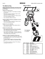
Page 13: ...l are seated firmly in place Check two 2 plug in connections for Sensor and its Control are seated firmly in place Check that Blower Wheel spins freely Symptom Motion mode does not operate fan at certi fied air flow rate Check two 2 plug in connections for Sensor and its Control are seated firmly in place Symptom Fan runs erratically Check that Blower Wheel is firmly attached to Motor shaft and bo...

Page 14: ...h natural wear of finish i Fans in commercial or nonresidential use or j damage caused by fire flood or other act of God This warranty covers only Fans sold in the United States or through U S distributors authorized by Broan EXCLUSION OF DAMAGES BROAN S OBLIGATION TO PROVIDE REPLACEMENT PARTS OR REPAIR OR REPLACE AT BROAN S OPTION SHALL BE YOUR SOLE AND EXCLUSIVE REMEDY UNDER THIS LIMITED WARRANT...

Page 15: ...ño de la casa Registre su producto en línea en www broan com register Fácil instalación en construcciones nuevas y en aplicaciones de conversión Índice Advertencias y precauciones 2 Instalación típica 2 Instalación en una construcción nueva 3 Instalación de conversión 7 Funcionamiento 12 Limpieza y mantenimiento 12 Resolución de problemas 12 Piezas de servicio 13 Garantía 14 ...

Page 16: ...re una tina o ducha siempre que se conecte a un GFCI interruptor accionado por pérdida de conexión a tierra en un circuito de derivación protegido 9 Esta unidad debe estar conectada a tierra Instalación típica PRECAUCIÓN 1 Solo para usarse como medio de ventilación general No debe usarse para la extracción de materiales o vapores peligrosos o explosivos 2 Este producto está diseñado para instalars...

Page 17: ...5 2 cm para obtener un desempeño óptimo Aunque el uso de otros sistemas de conductos es aceptable puede afectar al desempeño Tapa de techo o tapa de pared se recomienda que tenga regulador de tiro integrado Cinta para sellar las conexiones de los conductos Cableado eléctrico y suministros según los requisitos de los códigos locales 1 Saque el producto de su empaque 2 Instale el marco de montaje La...

Page 18: ... a ambos lados del marco de montaje para fijar la cubierta en su lugar No doble la cubierta Tornillos de la bolsa de piezas Las bridas superior e inferior se instalan por fuera de la cubierta Introduzca la pestaña en la ranura del interior de la cubierta Tornillo de la bolsa de piezas Reductor de 6 a 4 pulg 15 2 a 10 2 cm para modelo ZB80M solamente Cinta Cinta Cinta Conductos de 6 pulg 15 2 cm Co...

Page 19: ...ROL ROJO INTERRUPTOR MAESTRO VENTILADOR INTERRUPTOR MAESTRO DE ENCENDIDO APAGADO INTERRUPTOR DE ENCENDIDO MANUAL PLACA DE AGUJERO CIEGO RECEPTÁCULOS LÍNEA DE ENTRADA DE 120 VCA CAJA DEL INTERRUPTOR NEGRO BLANCO ROJO AZUL Se compra por separado INTERRUPTOR DE CONTROL SENSOR TIERRA Verde o sin aislamiento NARANJA CAFÉ Vea los detalles de la sección FUNCIONAMIENTO en la página 26 El interruptor MAEST...

Page 20: ...to limpieza mantenimiento y resolución de problemas La cubierta protege la unidad durante la construcción Retírela antes de instalar la rejilla Instale el material del cielo raso Recorte alrededor de la cubierta Conecte el sensor PRECAUCIÓN Si el motor estaba desconectado se debe desconectar la electricidad vea la página 16 ADVERTENCIA punto 2 antes de insertar los enchufes del motor en el conjunt...

Page 21: ...que no esté dañado Si encuentra algún daño NO CONTINÚE CON LA INSTALACIÓN de este producto Encargue la reparación a personas debidamente capacitadas Saque la hoja de instrucciones Retire la cubierta protectora del empaque Proceda con el paso 12 1 Saque el producto de su empaque 2 Apague la unidad 4 Examine el cableado 3 Agrande la abertura del cielo raso y retire el ventilador existente Regla Lápi...

Page 22: ...tire el conjunto del ventilador 6 Retire el panel de cableado 7 Inserte el marco de montaje Ambos lados Ponga a un lado el conjunto del ventilador Ponga a un lado el panel de cableado Ponga a un lado el tornillo Doble hacia arriba las cuatro pestañas Saque los tornillos del marco de montaje y póngalos a un lado ...

Page 23: ...ida que lo inserta en el marco de montaje Tire de los conductos existentes hacia el interior de la cubierta Introduzca la pestaña en la ranura del interior de la cubierta 10 Acople el conector de conductos y los conductos 8 Sujete el marco de montaje 9 Cubierta a presión Acople a presión Reductor de 6 a 4 pulg 15 2 a 10 2 cm para modelo ZB80M solamente Cinta Cinta Cinta Conductos de 6 pulg 15 2 cm...

Page 24: ...leado SENSOR CONTROL NEGRO BLANCO NEGRO NARANJA TIERRA BLANCO NEGRO TIERRA BLANCO NEGRO CAFÉ 120 VCA LÍNEA DE ENTRADA 14 2 ROJO INTERRUPTOR DE PARED MAESTRO VENTILADOR PLACA DE AGUJERO CIEGO RECEPTÁCULOS LÍNEA DE ENTRADA DE 120 VCA CAJA DEL INTERRUPTOR NEGRO BLANCO ROJO AZUL Se compra por separado TIERRA Verde o sin aislamiento INTERRUPTOR DE PARED MAESTRO Vea los detalles de la sección FUNCIONAMI...

Page 25: ...en la cubierta después de haber fijado el conjunto del ventilador Consulte el paso 6 sobre la instalación en una construcción nueva Retire la cubierta protectora antes de instalar la rejilla Tornillos de la bolsa de piezas Conecte el sensor PRECAUCIÓN Debe desconectar la electricidad vea la página 16 ADVERTENCIA punto 2 antes de insertar los enchufes del motor en el conjunto de control PARA PREVEN...

Page 26: ... pared del sensor control puede estar encendido o apagado 2 El ventilador funciona a un índice certificada de flujo de aire 3 Cuando el interruptor de pared de encendido manual está apagado el ventilador pasa al modo de retardo de tiempo Retardo de tiempo El ventilador continúa funcionando a una velocidad de flujo de aire certificado hasta que haya pasado por el usuario ajustable retardo de tiempo...

Page 27: ... Compruebe que la rueda del ventilador gire sin obstrucciones Síntoma El modo de movimiento no hace funcionar el ventilador al índice nominal de flujo de aire Asegúrese de que los dos 2 conectores de enchufe del sensor y de su control estén bien afianzados en su lugar Síntoma El ventilador funciona de forma errática Compruebe que la rueda del ventilador esté firmemente acoplada al eje del motor y ...

Page 28: ...dio inundación u otro caso fortuito Esta garantía cubre sólo a los Ventiladores que se venden en los Estados Unidos o a través de representantes de los Estados Unidos autorizados por Broan EXCLUSIÓN DE DAÑOS LA OBLIGACIÓN DE BROAN DE PROPORCIONAR REPUESTOS O LA REPARACIÓN O EL REEMPLAZO A DISCRECIÓN DE BROAN SERÁ LA ÚNICAY EXCLUSIVA COMPENSACIÓN BAJO EL AMPARO DE ESTA GARANTÍA LIMITADAY LA ÚNICAY ...

Page 29: ... client Enregistrez votre produit en ligne sur www broan ca register asp Installation facile lors de construction neuve ou de rénovations Table des matières Avertissements et mises en garde 2 Installation type 2 Installation dans une construction neuve 3 Installation lors de rénovation 7 Fonctionnement 12 Nettoyage et entretien 12 Dépannage 12 Pièces de rechange 13 Garantie 14 BB0053 ...

Page 30: ...joncteur de fuite à la terre DDFT 9 Cet appareil doit obligatoirement être mis à la terre Instalation type ATTENTION 1 Réservé exclusivement à la ventilation générale Ne pas utiliser pour évacuer des matières ou des vapeurs dangereuses ou explosives 2 Ce produit est conçu pour être installé dans des plafonds plats Le détecteur ne pourra fonctionner de façon fiable si ce produit est installé dans u...

Page 31: ...recommandé pour une meilleure performance Du conduit différent est acceptable au prix d une performance inférieure Capuchon de toit ou de mur recommandé avec clapet intégré Ruban adhésif pour l étanchéité des joints Câblage et fournitures électriques en fonction des exigences du code local 1 Retirer l emballage 2 Installer le cadre de montage Le sachet de pièces contient une plaque de câblage et s...

Page 32: ... pincer la glissière de chaque côté du cadre de montage pour verrouiller le boîtier en place Ne pas pincer le boîtier Vis du sachet de pièces Les rebords supérieur et inférieur vont à l extérieur du boîtier Introduire la languette dans la fente à l intérieur du boîtier Vis du sachet de pièces Encliqueté Réducteur de 6 po à 4 po fourni avec certains modèles Ruban adhésif Conduit de 6 po Ruban adhés...

Page 33: ...TEUR CONTRÔLE DU CAPTEUR INTERRUPTEUR PRINCIPAL MARCHE ARRÊT INTERRUPTEUR MANUEL RÉCEPTACLES BOÎTIER D INTERRUPTEURS NOIR BLANC ROUGE BLEU INTERRUPTEUR DE COMMANDE DU CAPTEUR Mise à la terre VERT ou nu ORANGE BRUN LIGNE D ENTRÉE DE 120 VCA Acheter séparément PLAQUE DE CÂBLAGE BE0034F Voir la sec tion FONC TIONNEMENT à la page 26 pour tous les détails L interrupteur MAÎTRE ac tionne ou arrête le ve...

Page 34: ...insi que pour le dépannage Le masque protège l appareil pendant les travaux Retirer le masque avant d installer la grille Installer le matériau du plafond Découper autour du boîtier Brancher le capteur ATTENTION Si le ventilateur a été débranché l alimentation doit être coupée avant d insérer les fiches du moteur dans l ensemble de commande voir page 16 AVERTISSEMENT point 2 POUR ÉVITER D ENDOMMAG...

Page 35: ...uteau universel Matériaux nécessaires Ruban adhésif pour l étanchéité des joints Un conduit rigide existant nécessite l ajout d une courte section de conduit flexible Câblage et fournitures électriques en fonction des exigences du code local Outils nécessaires Tournevis électrique avec embout Phillips Tournevis Phillips Tournevis à lame plate Pinces Pince à dénuder Pince coupante AVERTISSEMENT Ava...

Page 36: ...n 5 Retirer l ensemble ventilateur 6 Retirer le panneau de branchement 7 Installer le cadre de montage Des deux côtés Mettre de côté l ensemble ventilateur Mettre de côté le panneau de branchement Mettre de côté la vis Replier les quatre languettes Retirer et conserver les vis du cadre de montage ...

Page 37: ...ier en insérant celui ci dans le cadre de montage Introduire le conduit existant dans le boîtier 10 Fixer le raccord de conduit et le conduit 8 Fixer le cadre de montage 9 Encliqueter le boîtier Introduire la languette dans la fente à l intérieur du boîtier Encliqueté Réducteur de 6 po à 4 po fourni avec certains modèles Ruban adhésif Conduit de 6 po Ruban adhésif Conduit de 4 po Ruban adhésif ...

Page 38: ...IR ORANGE INTERRUPTEUR PRINCIPAL Mise à la terre BLANC NOIR Mise à la terre BLANC NOIR BRUN LIGNE D ENTRÉE 120 VCA 14 2 ROUGE BE0035F CONTRÔLE DU CAPTEUR INTERRUPTEUR PRINCIPAL PLAQUE DE CÂBLAGE RÉCEPTACLES LIGNE D ENTRÉE 120VCA BOÎTIER D INTERRUPTEUR NOIR BLANC Acheter séparément Mise à la terre VERT ou nu ORANGE BRUN BE0036F Voir la section FONCTIONNEMENT à la page 26 pour tous les détails L int...

Page 39: ...ettre le masque dans le boîtier après fixation de l ensemble ventilateur Voir Installation dans une construction neuve étape 6 Retirer le masque avant d installer la grille Vis du sachet de pièces Brancher le capteur ATTENTION L alimentation doit être coupée avant d insérer les fiches du moteur dans l ensemble de commande voir page 16 AVERTISSEMENT point 2 POUR ÉVITER D ENDOMMAGER LE MOTEUR LA COM...

Page 40: ...ans le mode chronométré lorsque l interrupteur manuel sur est éteint Minuterie Le ventilateur functionne à l écoulement de l air certifié jusqu à ce que l utilisateur minuterie réglable a expiré alors le ventilateur tourne à débit d air réglable par l utilisateur Pour régler le débit d air À l aide d un petit tournevis à lame plate tourner délicatement le bouton CFM pieds cubes par minute jusqu à ...

Page 41: ...n contrôle soient bien insérés dans les réceptacles Vérifier que la roue du ventilateur tourne librement Symptôme Le mode de détection de mouvement ne fait pas fonctionner le ventilateur à son débit homologué S assurer que les deux 2 connecteurs pour le capteur et son contrôle soient bien insérés dans les réceptacles Symptôme Le ventilateur fonctionne de manière erratique S assurer que la roue du ...

Page 42: ...ésente garantie ne couvre que les ventilateurs vendus au Canada ou par des distributeurs canadiens agréés par Broan EXCLUSION DES DOMMAGES L OBLIGATION PAR BROAN DE FOURNIR DES PIÈCES DE RECHANGE OU D EFFECTUER UNE RÉPARATION OU UN REMPLACEMENT AU CHOIX DE BROAN REPRÉSENTE VOTRE RECOURS UNIQUE ET EXCLUSIF EN VERTU DE LA PRÉSENTE GARANTIE LIMITÉE ET CONSTITUE L OBLIGATION UNIQUE ET EXCLUSIVE DE BRO...

Page 43: ......

Page 44: ...99045844A ...

Reviews: