


INSTALLATION
WARNING: To reduce the risk of fire, do not store or
use gasoline or other flammable vapors and liquids
in the vicinity of the heater.
CAUTION: High temperature, risk of fire, keep
electrical cords, drapery, furnishings, and other
combustibles at least 3 feet (0.9 m) from the front of
the heater and away from the side and rear.
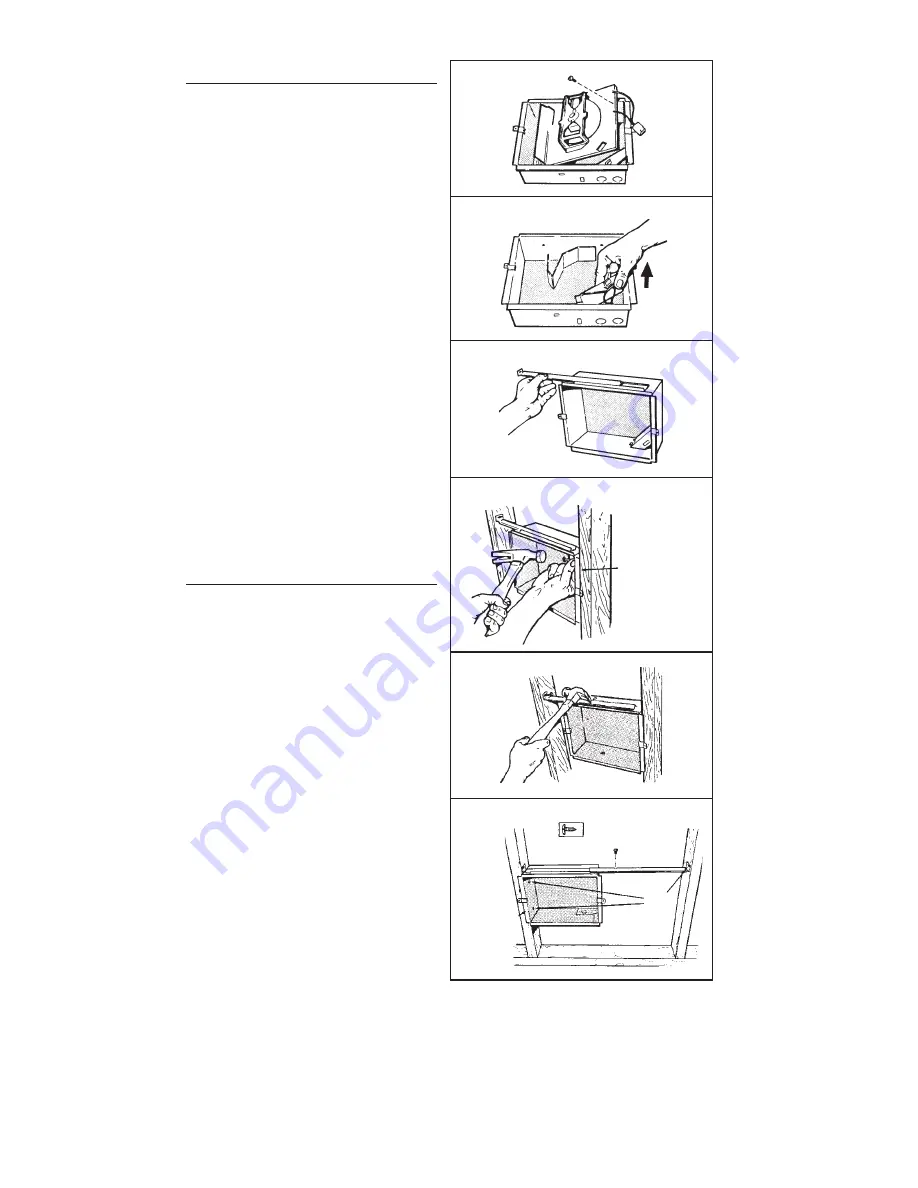
1. Remove the retaining screw, unplug wiring harness
and lift heater assembly from housing. (FIG. 2)
2. Slide the wiring cover out of housing. (FIG. 3)
(16”-ON-CENTER STUDS ONLY)
1. Choose which side of housing will be mounted
directly to a wall stud. Then, insert a mounting
bracket, from the opposite side, into the channel
at the top of housing. (FIG. 4)
NOTE
: Locate housing at least 6” from the floor and
any adjacent walls.
2. Use measuring guide on side of housing to posi-
tion housing so that it will be flush with finished
wall. Drive two (2) nails through the holes in side
of housing and into stud. (FIG. 5)
3. Extend mounting bracket, level housing, and nail
to other stud. (FIG. 6)
(24”-ON-CENTER STUDS ONLY)
1. Choose which side of housing will be mounted di-
rectly to a wall stud. From this side, push a mounting
bracket as far as possible into the channel at the
top of housing. (FIG. 4)
NOTE
: Locate housing at least 6” from the floor and
any adjacent walls.
2. Use measuring guide on side of housing to posi-
tion housing so that it will be flush with finished
wall. Drive two (2) nails through the holes in side
of housing and into stud. (FIG. 5)
3. Secure the two (2) mounting brackets together (with
screw supplied). Level housing and nail to opposite
stud, as shown. (FIG. 7)
WIRING
Installation work and electrical wiring must be
done by a qualified person(s) in accordance with
all applicable codes and standards, including fire-
rated construction codes and standards.
(ALL INSTALLATIONS)
1. Feed electrical power cable through open knockout
in corner of housing and attach with appropriate
connector. Allow 6” of wire inside of housing.
NOTE
: Use other housing knockout when wiring
units in parallel.
2. Connect black to black, white to white, green to
green or bare wire. Replace wiring cover. (FIG. 8)
FIG. 2
FIG. 3
FIG. 4
FIG. 5
MEASURING
GUIDE
FIG. 6
FIG. 7
MEASURING
GUIDES
NAIL
HERE