


e-mail:
voice:
360.854.9559
fax:
866.783.1742
8
AVR-8 Installation and Operation Manual
INSTALLATION
INSTALLATION
Installation of the AVR-8 in high RF environments should be performed with care.
Shielded cable is suggested for all control, audio inputs and outputs. All shields
should be tied to the EGND terminals. The station ground should be connected to
the chassis ground screw located on the far right side of the AVR-8 as viewed from
the rear. It is recommended that all cables connected to the AVR-8 be looped
through ferrite cores to suppress RF. Surge protection with RF filtering such as the
Tripp Lite “ISOBAR 4 or 6” is also suggested for the wall transformer. The pur-
chase of an inexpensive UPS will provide back-up power in case of a power outage.
INPUTS
Note: The 5-vdc TTL/CMOS compatible inputs are configured as a divider. A low
input must be between 0 and + .6vdc, while a high must be b 4.00 and +
5.00 vdc. This should help in noisy (RF, etc) environments.
The eight inputs can be set up to be either normally open or normally closed. Upon
power up or by pressing the reset button, the state of the inputs will be read and
accepted as the normal non-alarm state. When any particular input changes state, it
will be considered an alarm and initiate a call out. The AVR-8 will then look at the
call-out list associated with the alarmed input and begin calling the first number on
the list. If you want that input to first call a pager then be sure to list “9" first in your
call out list. For example, if you want a page to be called out and then call number
1 on the dial out list for input 5 then program 91 into the input 5-dial list. The first
number will be called on the dial list and the alarm message will be played the num-
ber of times that is programmed into the “repeat” memory. If there is no acknowl-
edgment the AVR-8 will go on to the next number and so on until all numbers stored
in that inputs dial list have been called. This process will then be repeated for the
number of times stored in the “lap” memory. The repeat and lap memories are glob-
al and are the same for all inputs.
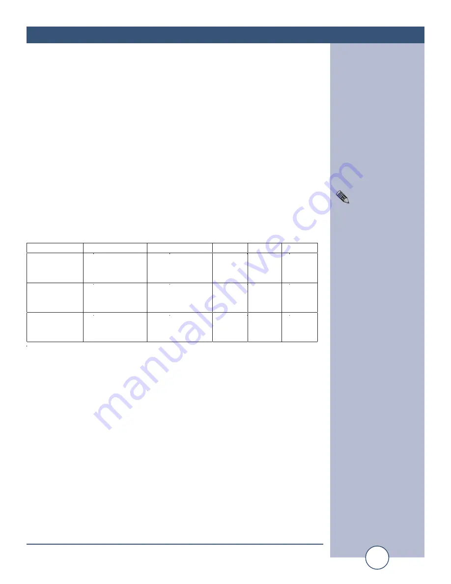
Function
Terminal A
Terminal B
JP-A
JP-A
JP-B
Optically
Isolated Dry
Contacts
Ground
Cathode of Opto-
Isolator
1 & 2
3 & 4
2 & 3
Optically
Isolated Wet
Contacts
Anode of the
Opto-Isolator
Cathode of the
Opto-Isolator
2 & 3
2 & 3
TTL/CMOS
compatible
5 volt logic
Ground
Logic input with
pull-ups
1 & 2
3 & 4
1 & 2
NOTE:
All inputs must be
equal to or greater than
100ms in duration.


