


LBC-SPH8-1HB7-EIR User’s Manual
Link Bridge
TM
HDBaseT 7x Transmission System
Broadata Technical Support, (800) 214-0222
8
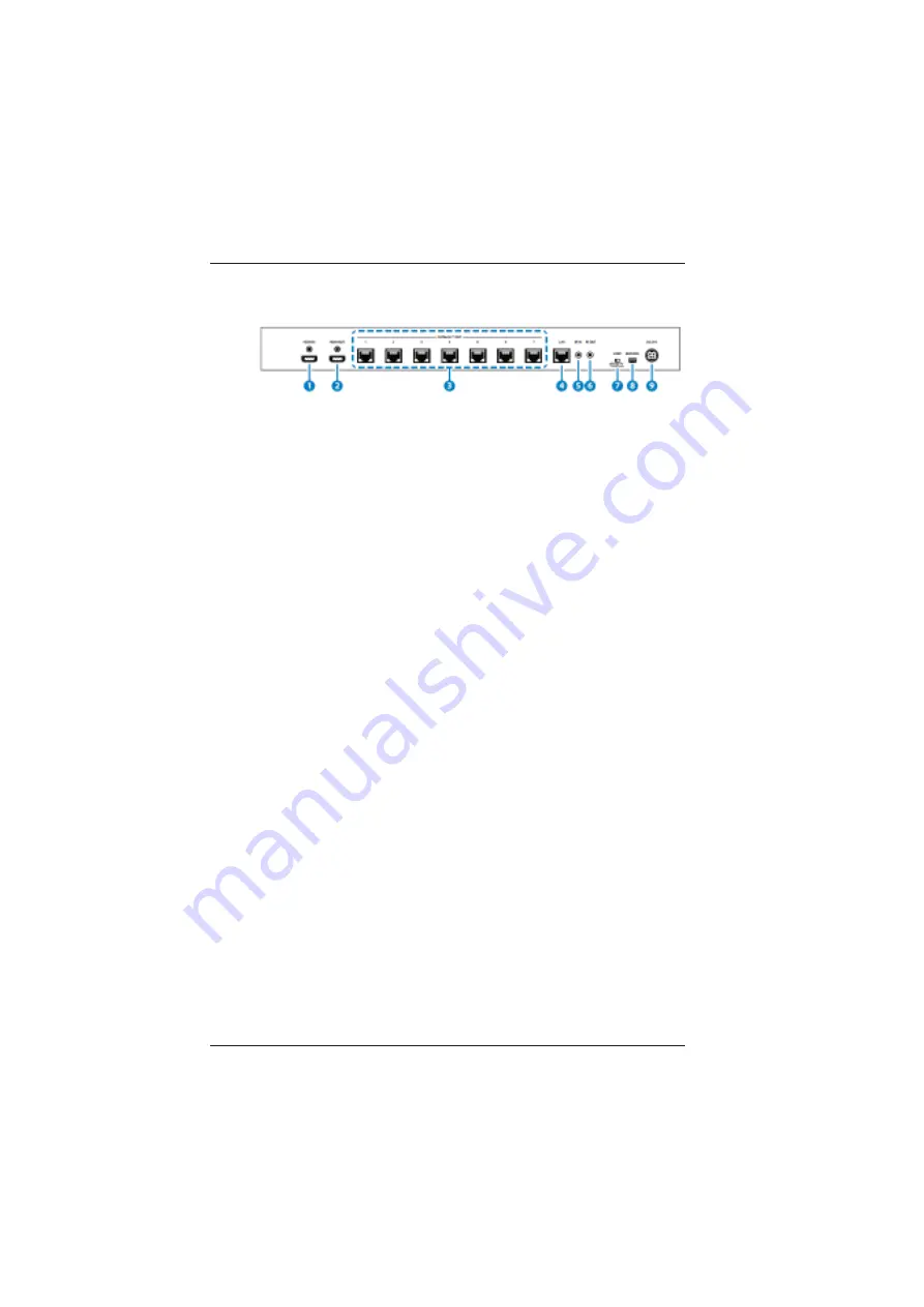
2.2 Rear Panel
1.
HDMI IN:
Connect to HDMI equipped source equipment such as a DVD/
Blu-ray player or game console.
2. HDMI OUT:
Connect to a HDMI display for local monitoring of the HDMI
signal or cascade to another Splitter.
3. CAT5e/6/7 OUT 1~7
:
Connect to CAT-5e/6/7 to HDMI Receivers (with or without
PoH) with a single CAT-5e/6/7 cable each to extend the HDMI
signal up to 100m.
4.
LAN
:
Connect to an active network for LAN support. When any
compatible LAN equipped receivers are connected, this allows
the network access (including internet access if available) to
be shared. Connect any Ethernet equipped device to the LAN
port of a receiver for that device to share the network/internet
access.
Warning
: DO NOT connect the LAN connection with
any of the CAT-5e/6/7 outputs, doing so may trigger a
power shut down and may damage the device
5.
IR IN
:
Connect the supplied IR Receiver cable for IR signal reception.
Ensure that the remote being used is within direct line-of-sight
of the IR Extender.
6
. IR OUT
:
Connect the supplied IR Blaster cable for IR signal transmission.
Place the IR Blaster in direct line-of-sight of the equipment to
be controlled.


