3.
"SETTING UP" THE SYSTEM
When the installation wiring has been completed and before the
CCU
cover is replaced
the system should be "set-up".
A
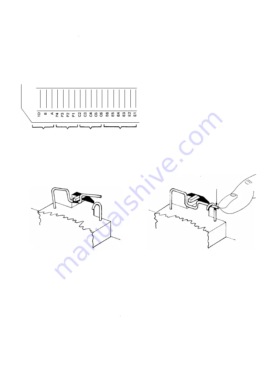
block of eighteen "safety pin" type switches is mounted
at the lower left hand corner of the
CCU,
see
fig 2
and
figs. 4
and
5.
I I I I I I I
I
I I I I I I I I I I
"Call Bar-
"Progr -
ring
ammed
Switches
Ringing
Switches
"Call
Barring
Switches
'OPEN' (RELEASED)
"Exist"
Switches
FIG.4
ARRANGEMENT OF
FACILITY SWITCHES
USE FINGERTIP TO GENTLY RELEASE
OR OPERATE TH!= "LATCH"
'CLOSED' (OPERATED)
FIG.5
SAFETY-PIN TYPE SWITCH
"Exist" Switches.
"Exist" Switches. Switches E
1
to E6 are used to open the extensions for use.
For an equipped extension the relevant E Switch must be open, if an extension is not provided
the E switch must be closed. This is to ensure that the correct tone is returned to the caller
Should a spare extension number be inadvertantly dialled
NU
will be returned, if the
extension is "open" ringing will be connected and ring tone returned to the caller.
5.


