


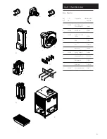


15.0 Changing Components
50
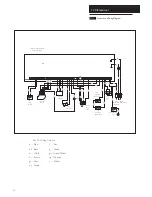
Combustion
Box Base
Central Insulation Panel
Support Bracket
Burner
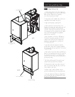
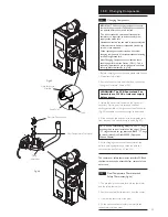
15.12
Heat Exchanger Lower Insulation Pad
(Fig. 60)
1. Remove all components in the base of the airbox.
2. Remove the burner (see section 15.10).
3. Remove the four bolts securing the combustion box base.
Remove the combustion box base.
4. Pull the central insulation panel down from the centre of
the heat exchanger and remove the lower insulation pad.
5. Fit the new insulation pad and reassemble in reverse
order.
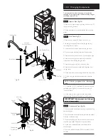
15.13
Heat Exchanger Upper Insulation Pad
(Fig. 60)
1. Remove all components in the base of the airbox.
2. Remove the burner (see section 15.10).
3. Remove the heat exchanger (see section 15.11).
4. Remove the four bolts securing the combustion box base.
Remove the combustion box base.
5. Pull the central insulation panel down from the centre of
the heat exchanger.
6. Fit the new insulation pad and reassemble in reverse
order.
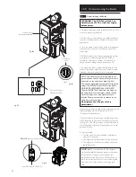
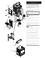
15.14
Output Rotary Selector Switch
(Fig. 61)
1. Ensure that the electrical supply to the boiler is isolated
and undo the screw securing the Output Selector Switch
Cover.
2. Note the position of the control knob. Pull the knob off
the Selector Switch. Ease the bracket to the right and
forwards, disengaging the keyhole slot from the locating
screw.
3. Slacken the locknut holding the Output Selector Switch to
the mounting bracket, remove the Switch and disconnect
the electrical plug.
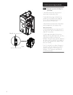
4. Take the new Output Selector Switch, connect the
electrical plug and locate on the mounting bracket.
5. Secure the new Selector Switch with the locknut and refit
the knob. Engage the keyhole slot in the bracket over the
screw on the boiler.
6. Turn the knob to the position previously noted and refit
the cover. Apply the label supplied in the kit over the screw.
Combustion Box Base
Securing Screws
Burner Securing
Screws
Fig. 60
Upper Insulation
Pad
Lower Insulation
Pad
Output Selector
Switch Cover
Output Selector
Switch & Bracket
Output Selector
Switch
Fig. 61
Label


